Greencube (IO-117) – Setup, Software, and Operation

Typical Greencube Pass Providing DX Possibilities

Typical Greencube Pass Providing DX Possibilities

Greencube (IO-117) is a Medium Earth Orbit (MEO) satellite that carries a 70cm digipeater. This satellite can provide DX contacts covering a wide area around an Amateur Radio satellite ground station. Putting together a station and the necessary software to use Greencube is not difficult. If you already have a computer-controlled satellite ground station that works on 70cm, you may already have most of what is needed. We’ll cover Greencube (IO-117) setup in detail in this article.

Operating with Greencube – What’s Required

Greencube (IO-117) requires the following for successful contacts via its digipeater:

  • A directional antenna with at least 12 dBi gain
  • A 70cm SSB/FM capable Transceiver with a soundcard interface and at least 25 watts of output at the antenna
  • Software to control the Transceiver to correct for Doppler shift and provide antenna tracking control or pointing information
  • A computer running modem software and a Greencube Terminal Program
  • A low-noise preamp at the antenna is recommended

Greencube Satellite Antennas

Satellite Antennas Tracking Greencube (IO-117)

Tower Mounted Satellite Antennas Tracking Greencube

We have three different antenna combinations that are Greencube capable here:

ARR Satellite Preamp

ARR Satellite Preamp

All three antennas have Advanced Receiver Research Low-Noise preamps which are powered via the associated antenna’s coax feedline. Unfortunately, the ARR preamps are no longer available. A good alternative would be the SSB Electronic SP 70 preamp. I recommend choosing a preamp that can be sequenced using coax power from your transceiver if your transceiver supports coax-powered preamps. This approach ensures that your preamps are protected from transmit power in most operational scenarios.

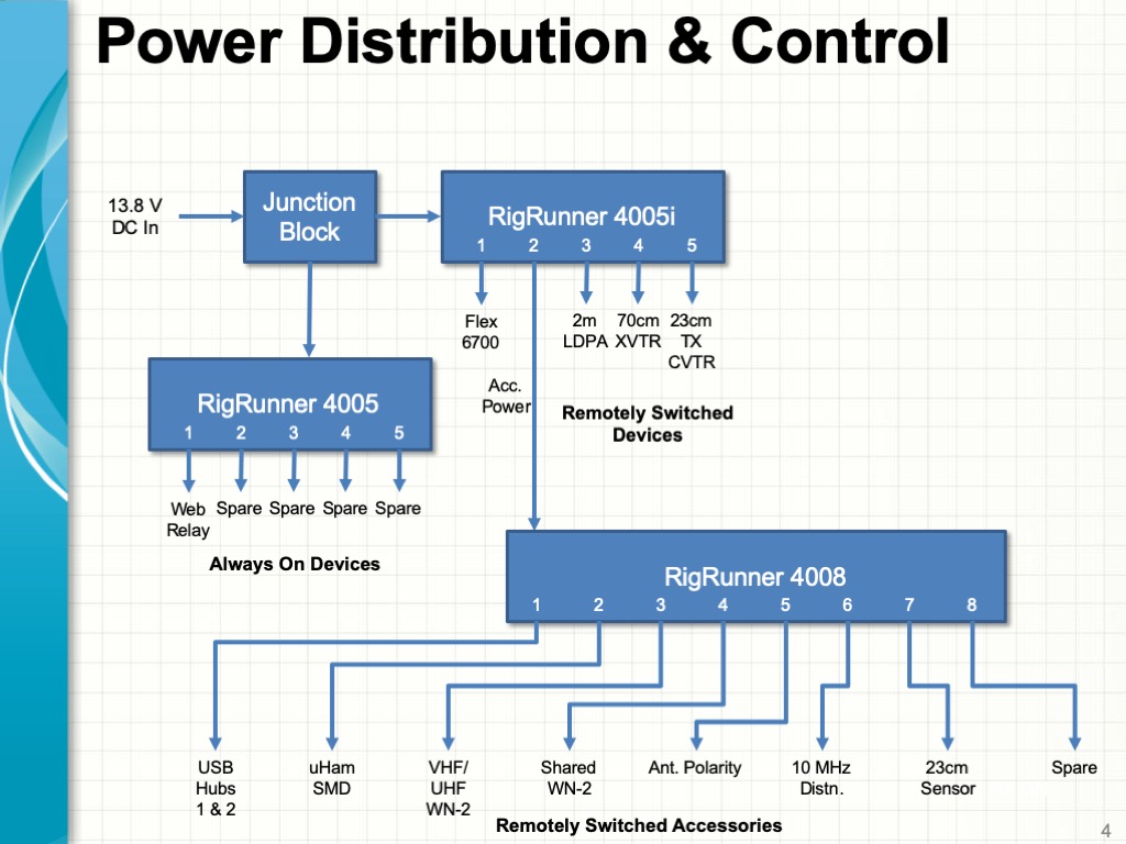
Radio, Computers, and Power

New IC-9700

Icom IC-9700 Transceiver

All of our Greencube (IO-117) setups use an Icom IC-9700 Transceiver.

We use two computers to run our stations:

  • A Mac (iMac or MacbookAir) running MacDoppler to control antenna tracking and to control our IC-9700 to perform Doppler correction
  • A Windows PC running the modem, terminal client software, and a logger for using Greencube’s digipeater and for decoding telemetry
Greencube (IO-117) Setup - Transportable Ground Station Radio and Computers

Transportable Ground Station Radio and Computers

Using the two computers means that both must simultaneously control the IC-9700 via the radio’s CAT interface. This is easily accomplished with the IC-9700 by using both the CI-V and USB CAT interfaces. The radio’s CI-V interface is used with MacDoppler, and the USB interface is used with the Windows PC to connect the IC-9700’s Rx and Tx audio to the modem SW and to provide for PTT via a COM port.

We use AC power for our fixed and transportable setups.

Portable Solar-Battery Power System

Our portable setup uses solar power consisting of two 90-watt foldable panels, an MPPT charger system, and a pair of A123 LiPo batteries. We’ll share more about our portable and transportable setups in subsequent posts.

Software

Greencube Client and Modem Software

Greencube Terminal and Uz7HO Modem Software

We use the following software for our Greencube (IO-117) ground station:

MacDoppler runs on a Mac computer (iMac or Macbook Air), and the rest of the software runs on a Windows PC.

The links above include instructions for setting up each of the software applications. The following are some notes on Greencube (IO-117) setup for each software component.

MacDoppler

Greencube (IO-117) Setup - MacDoopler Configuration for Greencube

MacDoopler Configuration for Greencube

The Greencube (IO-117) setup in MacDoppler configures the IC-9700 Transceiver to operate in simplex SSB digital mode. This is the SSB-D choice in MacDoppler’s Modes tab for Greencube.

MacDoppler Uplink and Downlink VFO Offsets

MacDoppler Uplink and Downlink VFO Offsets

You’ll want to select SSB-D mode in MacDoppler to track Greencube and configure the IC-9700 to work with the Greencube digipeater. Setting the uplink and downlink offsets to -1.200 KHz will place Greencube’s packet transmissions in the middle of the IC-9700’s passband.

UZ7HO Soundmodem

UZ7HO Sound Modem Greencube Packet Decoding Greencube Packets

UZ7HO Sound Modem Greencube Packet Decoding Greencube Packets

There is a specific version of UZ7HO’s Soundmodem for use with Greencube (see the link above to download greentnc.zip). The soundcard and PTT COM port interfaces provided via the USB connection to the IC-9700 must be configured in Soundmodem.

Soundmodem Devices Settings

Greencube (IO-117) Setup - UZ7HO Soundmodem - Devices Setup

UZ7HO Soundmodem – Devices Setup

The USB connection from the IC-9700 to a Windows PC will create a pair of sound devices (in this example, USB Audio CODEC) and a COM port (in this example, COM15) for CAT and PTT control. These must be properly configured in the Settings – Devices choice on the Soundmodem main menu.

Soundmodem Modem Settings

UZ7HO Soundmodem - Modem Setup

UZ7HO Soundmodem – Modem Setup

The Settings – Modems choice on the Soundmodem main menu brings up this dialog. The settings are the default ones. Note that Soundmodem has two modes – GreenCube 1200bd and GreenCube 300bd. The GreenCube 1200bd setting is normally used for digipeater operation, including decoding telemetry when enabled. You’ll need to use the GreenCube 300bd setting to decode telemetry if Greencube’s digipeater is turned off.

IC-9700 Transceiver Settings

There are some important adjustments to the configuration of the IC-9700 that need to be made for Soundmodem to work properly with the transceiver.

IC-9700 CI-V Settings

IC-9700 CI-V Settings

Configuring the CI-V USB Port to Unlink from [REMOTE] is necessary to allow it to function independently for the other interfaces.

IC-9700 USB AF Output Settings

IC-9700 USB AF Output Settings

You’ll want to set the AF Output Level of the USB interface to about 25% of the maximum and adjust the Windows audio control in Control Panel to get a display on the Soundmodem waterfall of about the intensity shown above.

IC-9700 USB Modulation Input Settings

IC-9700 USB Modulation Input Settings

Setting up the Tx audio levels is important to avoid overdriving the Transmitter. A good place to start is to set the USB Mod Level in the IC-9700 to about 25%.

IC-9700 Tx Drive Setting for One ALC Bar

IC-9700 Tx Drive Adjustment for 1-2 ALC Bars

Then adjust the Windows audio control in Control Panel to get full transmitter output power with only one or two bars of ALC indication on the IC-9700’s ALC meter when transmitting via the Greencube Terminal client. This adjustment is an essential part of your Greencube (IO-117) setup.

OZ9ARR’s Greencube Terminal Setup

Greencube Terminal and Modem Software

Greencube Terminal and Modem Software

A client program is required to format and decode the packets from Greencube. We are using OZ9ARR’s Greencube Terminal for this purpose. This program includes a macro button capability to help you format Greencube Tx packets and includes some nice capabilities for logging contacts and identifying new DXCCs, Grids, and Stations that you have not yet worked.

Greencube (IO-117) Setup - Greencube Terminal Setup

Greencube Terminal Setup

We are using Greencube Terminal with N3FJP’s ACLog to log contacts made with Greencube. This makes it easy to export our contacts to an adif file after each Greencube operating session and import them into our main logger. We also periodically export an adif file containing all of our satellite contacts from our main logger and provide access to this file so Greencube Terminal can determine what we’ve worked before. OZ9ARR’s Greencube Terminal webpage thoroughly explains how to set up and use the program.

DK3WN’s Greencube Telemetry Decoder

DK3WN's Greencube Telemtry Decoder

DK3WN’s Greencube Telemetry Decoder

Greencube periodically sends Telemetry information. You can decode it by using DK3WN’s Greencube Telemetry Decoder with Soundmodem. You can download the decoder and see how to install it on DK3WN’s webpage.

Making Contacts with Greencube

Greencube Terminal and Modem Software

Greencube Terminal and Modem Software

With your Greencube (IO-117) Setup complete, you should be ready to make some contacts! Begin by starting up all of the software and configuring MacDoppler to track Greencube in SSB-D mode. When Greencube is in range, you should see Greencube’s packet transmission being displayed in Soundmodem’s waterfall, and you should be able to hear the packet bursts on your Transceiver. Adjust the Soundmodem decode pointers by dragging them with your mouse to center them in the waterfall traces received in Soundmodem. The setting should be around 1400 – 1500 Hz. Also, make sure that GreenCube 1200db mode is selected in Soundmodem. You should see packets being decoded by Soundmodem.

Greencube (IO-117) Setup - CQ Button

CQ Button

Greencube (IO-117) Setup - INFO Button

INFO Button

Greencube (IO-117) Setup - RRR Button

RRR Button

Greencube (IO-117) Setup - 73 Button

73 Button

You can configure the Shortcut buttons to handle the steps needed to make a contact. The images above show the setup of the buttons that we are using here.

Greencube Terminal Working JH8FIH

Greencube Terminal Working JH8FIH

You’ll want to set the Tx delay for 0 – 2 seconds to give your preamp time to recover from transmitting before you receive your digipeater packets back from Greencube.

You can begin to make a contact by either clicking on another station’s CQ to load the station’s callsign or by just calling CQ yourself. Next, use the INFO button to send your callsign and grid square and then the RRR and 73 buttons to complete your contact. When you are done, you can right-click on the last packet in the exchange or on the station’s callsign that you have worked in one of the right windows to log the contact. That’s all there is to it!

Note that you’ll want to confirm that Greencube has heard and digipeated each of your transmissions. Collisions, fading, and other effects will often cause your packets to not be digipeated, and you’ll need to repeat your transmission until it is digipeated by Greencube.

You can also use the digipeater in store-and-forward mode by setting a long TX Delay (the number is in seconds). This can be as long as several hours to allow you to have Greencube digipeat your packet on the other side of the world! Note that store and forward contacts do not count for operating awards such as Worked All States, VUCC, or DXCC.

The video above shows Uz7HO Soundmodem and OZ9AAR’s Greencube Terminal being used to make contacts during a Greencube pass. the video also demonstrates some of Greencube Terminal’s features for identifying unworked calls and grids. You’ll want to spend some time reading OZ9AAR’s webpage to learn about and take maximum advantage of the many features Greencube Terminal can provide.

More Fun With Greencube

This article is the second in a series that we are working on. You view the other articles via the links below. This is a work in progress, and we’ll be creating additional Greencube-related posts in the near future:

You can also read more about our Satellite Ground stations here.

Fred, AB1OC

Tech Night – EME II: Station Construction and Operation

EME II - Station Construction and Operation

EME II Tech Night – Station Construction and Operation

We recently did a second Tech Night Program on EME as part of the Nashua Area Radio Society’s Tech Night program. I wanted to share the presentation and video from this Tech Night so that our readers might learn a little more about how to build and operate an EME station for the 2m band.

January 2021 Tech Night – EME II: Station Construction and Operation

You can view the Tech Night presentation by clicking on the video above. Here’s a link to the presentation that goes with the video. You can learn more about the Nashua Area Radio Society’s Tech Night program here. There is a demonstration of an actual live EME contact on the 2m band at 57:57 in the video.

The first Tech Night in the EME Series was about Getting Started in EME Communications. You can view that Tech Night here.

We are in the process of upgrading our EME station to include adaptive polarity. you can read more about that project here.

A key part of optimizing our EME Station was to reduce RFI from the network in our home. You can read about the installation of Fiber Optic Networking to reduce RFI and improve our EME station’s performance here.

Fred, AB1OC

EME Station 2.0 Part 12 – Station Software

EME Operating Position

EME Operating Position

Software is a big part of most current EME stations. The JT65 Protocol, which was created by Joe Taylor, K1JT, has revolutionized EME operations. It has made it possible for modest single and two yagi stations to have lots of fun with EME.

Phase 1 of our 2m EME station software and hardware uses manual switching/selection of receive polarity. This Phase is about integrating all of the station components together and sorting out operational issues. After some experimentation, we have settled on a dual-decoder architecture for the First Phase of our 2m EME Station.

You can learn more about the Phase 1 EME hardware setup at our station here.

EME Software Environment

EME Station Block Diagram - Phase 1

EME Station Block Diagram – Phase 1

The diagram above shows the current configuration of our 2m EME station. As explained in a previous article in this series, we are using a FUNCube Pro+ Dongle with the MAP65 application as our primary JT65b decoder, and we are using our IC-9700 Transceiver along with WSJT-X as a secondary, averaging decoder. Using multiple decoders has proven to be a significant advantage. It is quite common for one of the two applications to decode a weak signal that the other does not.

We use two custom applications (WSJTBridge and Flex-Bridge) to capture the Moon Azimuth and Elevation data generated by the MAP65 application and use it to control the rotators for our EME Antenna Array.

We have been experimenting with Linrad as a front-end to MAP65 and WSJT-X. Currently, we are using the NB/NR functions in MAP65 and our IC-9700 as an alternative to Linrad. We expect the add Linrad into our setup when we add Adaptive Polarity capabilities in Phase 2.

EME Software Operating Environment

EME Software Operating Environment (click for a larger view)

We use the DXLab Suite for logging and QSL’ing our contacts, along with several web apps to find potential EME contacts and determine the EME Degradation level on any given day.

The screenshot above shows most apps running during a 2m EME operating session.

MAP65 Application – Primary Decoder and Operating Application

MAP65 Software

MAP65 Software

We are using MAP65 as our primary decoder. It also controls our IC-9700 Transceiver when transmitting JT65b messages. MAP65 used the I/Q data from our FUNCube Pro+ Dongle to detect and decode all signals in the 2m EME sub-band. A waterfall window displays all of the signals on the band as well as a zoomed-in view of the spectrum around the current QSO frequency. MAP65 also generates heading data for our rotators as well as estimates for the Doppler shift between stations. The MAP65 application also provides windows that list all of the stations on the band and the messages they are sending.

EME QSOs via MAP65

EME QSOs via MAP65

The screenshot above shows the main MAP65 window during a QSO with HB9Q. Round trip delay (DT) and signal strength information (dB) are shown for each message that is decoded. The MAP65 application and a manual explaining how to set up and use the program for 2m EME can be downloaded here.

Moon Tracking and Rotator Control

Custom Rotator Control Apps

Custom Rotator Control Apps (WSJT-Bridge and FlexBridge)

We developed an application we call FlexBridge some time back as part of our ongoing project to remote our Satellite Ground Station using our Flex-6700-based SDR Remote Operating Gateway. This application includes functionality to operate Az/El rotator controllers based on UDP messages which contain tracking data. We wrote a second application, WSJT-Bridge, which reads the Moon heading data that either MAP65 or WSJT-X generates and sends UDP messages that enable FlexBridge to track the moon. The combination enables MAP65 to control tracking the moon in our setup.

Both of these applications are at an alpha stage, and we will probably separate the rotator control functionality from FlexBridge and make it into a dedicated application.

Antennas On The Moon

Antennas On The Moon

One of the first steps in the integration process was to carefully calibrate our rotators to point precisely at the moon. We got the azimuth calibration close using the K1FO Beacon in CT. We made final adjustments visually until our antennas were centered on the moon on a clear night.

EME Tower Camera at Night

EME Tower Camera at Night

We recently installed an additional IP camera which gives us a view of our EME tower. This is a useful capability as it enables us to confirm the operation of our rotator from our shack.

WSJT-X – Secondary Decoder

WSJT-X Software

WSJT-X Software

We also run WSJT-X as a second decoder using the received audio stream from our IC-9700 Transceiver. WSJT-X has more advanced decoding functions and can average several sequences of JT65b 50-second transmissions to improve decoding sensitivity. It only works on one specific frequency at a time, so we use it to complement the broadband decoding capability that MAP65 provides.

We can also transmit using WSJT-X, which enables us to use its Echo Test functionality to confirm that we can receive our own signals off the moon.

The WSJT-X application and a manual explaining how to set up and use the program for EME can be downloaded here.

Finding Contacts and Logging

Finding QSOs and Logging

Finding Contacts and Logging

We use the DXLab Suite for logging and QSL’ing our contacts. DXLab’s Commander application provides the interface between WSJT-X and our IC-9700 Transceiver. This enables the DXLab Suite to determine the current QSO frequency and mode for logging purposes.

MAP65 Software

MAP65 Software and DXKeeper’s Capture Window

We keep DXKeeper’s Capture Window open on the screen where we run MAP65 so we can easily transfer QSO information to our log as we make contacts.

We also use several web apps to find potential EME contacts and to get an estimate of the level of EME Degradation on any given day:

We are working on interfacing our instance of MAP65 to LiveCQ so that we can contribute spots when we are operating. More on this to come in a future article in this series.

Next Steps

We have a dual-channel coherent SDR receiver from Afedri in hand, allowing us to do Adaptive Polarity using MAP65. We will be upgrading our station hardware and software to support Adaptive Polarity in the near future.

We are planning some enhancements to our H-Frame to enable better alignment of our antennas along with improved reliability and stability when rotator our antennas. We will cover these enhancements in the next article in this series.

You can read more about our EME station project via the links that follow:

If you’d like to learn more about How To Get Started in EME, check out the Nashua Area Radio Society Tech Night on this topic. You can find the EME Tech Night here.

A key part of optimizing our EME Station was to reduce RFI from the network in our home. You can read about the installation of Fiber Optic Networking to reduce RFI and improve our EME station’s performance here.

Fred, AB1OC

6m VUCC In A Day – ARRL June VHF Contest

6M VUCC Operating Award

6M VUCC Operating Award

The 6m Band is one of my favorite bands. The combination of its unpredictability and the amazing openings that it can produce certainly makes 6m The Magic Band for me!

Fred’s (AB1QB) First Place Finish in NH – 2013 ARRL June VHF Contest

Fred’s New Hampshire First Place Finish in the ARRL June VHF Contest

I haven’t had the chance to work the ARRL June VHF Contest from our home station for several years. A combination of Nashua Area Radio Society activities and preparations for ARRL Field Day has taken a higher priority. ARRL June VHF is a great contest and I was looking forward to working it this year. A few days before the contest Anita and I were talking about the contest and she suggested that I do a 6m Digital Entry. E-skip has been pretty good on 6m this year and we wanted to sort out how we’d do digital and 6m for our upcoming 2020 Field Day Operation from our home so I decided to take Anita’s advice and focus on 6m Digital for June VHF. I entered the contest in the Low-Power Category.

June VHF Operating Setup

6m VUCC

AB1OC Operating in 2020 June VHF

We built a Remote Operating Gateway that allows our station to be operated both over the Internet and from any room in our home via our Home Network. I decided to set up a 6m Digital Station upstairs in our dining room so I could be with Anita more during the contest. The setup consisted of a laptop PC with an outboard monitor and a Flex Maestro as the client for the Flex 6700 SDR in our shack.

Completed Antenna Stack On New Tower

Completed Antenna Stack on our VHF Tower

We have three antennas for 6m – one on our VHF Tower and two via the SteppIR DB36 yagis with 6m kits on our main tower.

Delta Loop On Tower

SteppIR DB36 Yagis on our Main Tower

The three antennas can be pointed in different directions and selected instantly via the computer. This provided to be an advantage during the contest. I kept one on Europe, one point due West, and the third pointed at the Tip of Florida and the Caribean during the contest.

6m VUCC

Operating Setup – N1MM+ and WSJT-X

Having two monitors (the Laptop and an outboard one) allow me to arrange all of the N1MM+ Logger and WSJT-X windows for efficient operating. The image above shows a snapshot of the screen layout during the contest. N1MM+ has some nice features that integrated with WSJT-X to make it easy to spot new grids (Multipliers) and stations that have not yet been worked. The windows on the very right side allowed me to control antenna switching and monitor power and SWR while operating. I use the PSTRotator application (lower-left center to turn my antennas.

6m Band Conditions

6m VUCC

6m PSK Reporter On Sunday Evening

Band conditions on 6m were amazing from here in New England almost the entire contest period! The band was open right at the start of the contest on Saturday and remained open to 11 pm local time on Saturday evening. I was up early on Sunday and was working folks in the Northeastern Region right from the start. After being open all day on Sunday, the band shut down around 5 pm local time and I was afraid that the fun on 6m might be over. I ate some dinner and took a 45-minute nap and got back to my station at around 6:30 pm. About 15 minutes after I resumed, 6m opened again to most of the United States and I was able to work DM and DN grid squares in the Western States! The band stayed open right until the end of the contest at 11 pm local time.

What About the VUCC…

6m VUCC

100 Grids Worked on 6m

Conditions on 6m were so good on Saturday that I almost worked a 6m VUCC by 11 pm on Saturday evening when the band closed. I had 93 grids worked on 6m in just 8 hours! The band opened again early on Sunday morning and I worked my 100th grid square before 10 am – working a 6m VUCC in less than 18 hours!

6m VUCC

Final 6m Grids Worked

By the end of the contest, I had worked a total of 162 Grids! They ranged from the West Coast of the US to Western Europe and from Southern Canada to Northern South America.

6m VUCC

6m Grids Worked During 2020 June VHF

The image above shows most of the 6m grids that I worked plotted on a world map (the EU grids are not shown).

6m VUCC

Final Claimed Score

I was able to make a total of 402 unique contacts on 6m by the end of the contest with a final Claimed Score that was a bit over 65K. All of my 6m contacts during the contest were made using a combination of FT8 and FT4 modes on 6m.

New Ones on 6m for AB1OC

6m VUCC

AB1OC Worldwide 6m Grid Map

I was hoping to work some all-time new Grids and June VHF did not disappoint. I worked a total of 11 new Grids and one new DXCC (Dominica) on 6m during the contest. The image above shows my worldwide grid coverage including the new ones worked during June VHF (my grids in Argentina and Uruguay are not shown above). I now have worked 432 grids on 6m and have confirmed 408 of them with 63 DXCC’s worked and 62 confirmed on the Magic Band.

Summing It All Up…

I must say that I had as much fun working 6m during June VHF this year as I have ever had in any contest! The band openings on 6m were really good and I was busy making new contacts for the entire time that I operated. The combination of the 6m Band and the contest certainly made some Magic for me!

Fred, AB1OC

Perspectives on a 6m DX Opening

6m DX Opening to Europe - PSK Reporter

6m DX Opening to Europe – PSKReporter

I’ve had a chance to operate on the 6m DX this past week. We are approaching the prime time for the summer Es (E-Skip) season here in the Northeastern United States. As a result, I wanted to see how propagation on the 6m band might be unfolding during this spring Es season. I was fortunate to catch a typical limited DX opening on the 6m band between our location here in New England and Europe. I thought that it might be helpful for those who are relatively new to the 6m band to see what this was like.

DX Opening Begins - JTDX Software View

A 6m DX Band Opening Begins – JTDX Software View

I spent some time on and off yesterday calling CQ and monitoring the 6m band using the JTDX software and FT8 mode. FT8 now dominates most of the activity on the 6m band. This is a result of a combination of FT8’s weak-signal performance and available reverse beacon tools such as PSKReporter. As you can see from the JTDX screenshot above, the 6m band was basically only open to the United States here until about 16:58z. At that point, I weakly decoded CT1ILT. This station faded almost immediately and I was unable to make a contact.

Approximately 4 minutes later, the 6m band opened solidly to Spain and France and quite a few stations in this area of Europe appeared with relatively strong signals.

6m DX Opening to Europe - Spotlight Area Propagation

6m DX Opening to Europe – Spotlight Area Propagation (PSKReporter)

As you can see from the PSKReporter screenshot above (taken near the end of the band opening), the probation on 6m was quite strong but limited to a very specific area and heading in Europe. This is typical of limited double-hop Es propagation. We most likely had two Es clouds aligning in such a way that a narrow path of propagation had been created on the 6m band.

A 6m DX Band Opening In Full Swing - JTDX Software View

A 6m DX Band Opening In Full Swing – JTDX Software View

The view above shows the 6m band opening in full swing. I was hearing 5-6 strong stations from France, Spain, and Italy almost immediately. These stations are all on a relatively narrow range of headings center at about 65 degrees from my QTH. I am scrambling to work the stations that represented new grid squares for me. I am using JTAlert as a bridge to my logger (DXLab Suite) and it is telling me that 2-3 of the station in the mix are in grid square that I have not yet worked on the 6m band.

A 6m DX Band Opening Comes to an End - JTDX Software View

A 6m DX Band Opening Comes to an End – JTDX Software View

Like all good things, the 6m DX opening had to come to an end. As you can see above, the 6m band closed as rapidly as it opened, leaving me calling CQ with no takers to work in Europe.

Contacts Made During the 6m DX Opening

Contacts Made During the 6m DX Opening

The total duration of this opening was about 20 minutes. The contacts that I made during this period are shown above. During the brief opening, I was able to make a total of 11 contacts with a limited set of grid squares in Europe. Most of the signals were quite strong (see the Sent and Rcvd columns in my log above). During the opening, I worked 5 new grid squares that were centered around the border between France and Spain.

AB1OC 6m Grids Worked and Confirmed

AB1OC 6m Grids Worked and Confirmed

By this morning, three of the five new grids that I worked had already confirmed on LoTW. Just for fun, I plotted my 6m grid progress on the Gridmapper website. I keep a copy of the Gridmapper view of my log by my operating area as a reference that I use in conjunction with PSK Reporter to help me identify 6m band openings that might provide opportunities to work new grids.

I hope that this article gives you some idea of the nature of 6m DX openings. The opening described here is pretty typical in that:

  • The band open (and closed) suddenly without much warning
  • The propagation was very good with many strong signals being decoded and worked at once
  • The opening was of short duration lasting only about 20 minutes
  • The band closed as rapidly as it opened
Monitoring the 6m Band at AB1OC

Monitoring the 6m Band at AB1OC

In order to work 6m DX, this experience emphasizes the need to monitor the 6m band for DX openings on a regular basis. This is most easily done using PSKReporter. The pattern of DX openings on 6m to Europe from here in New England is such that EU DX openings typically begin south of us and progress northward. I use our Remote Operating Gateway, a Flex-6700 SDR based setup, to monitor the 6m band for DX openings while I work here in my office. You can see the 6m FT8 setup here in my office running in the monitor-mode above.

FlexRadio Maestro Console

FlexRadio Maestro Console

I use the Maestro here in my office as my SDR client.

I hope that this information has been useful to our readers. As you can see from this example, the 6m Band is called the Magic Band for good reason. It is very exciting to be able to catch and work a good DX opening on 6m. The FT8 mode has both increased the level of activity on the 6m band and made 6m available to many stations with simple antennas and 100W transceivers. You can learn more about how to get started with FT8 on 6m here.

As I sit here writing this, the 6m band just opened to Austria and Hungry! Have to go work some DX on the 6m band…

Fred, AB1OC

Winter Field Day 2020 Final Station Test

Source: Winter Field Day 2020 Final Station Test – Nashua Area Radio Society

Winter Field Day 2020 is almost here! A few weekends ago, several of us got our QTH to complete the final station test for our planned 5O operation in Winter Field Day (WFD). Activities including setup and testing of a new, Portable Networking Pod and three of our five planned Winter Field Day stations. We are planning to use the N1MM+ Logger in a networked configuration this year…

This article covers equipment and networking aspects of the Nashua Area Radio Society’s planned 5O setup for Winter Field Day 2020. All of our stations will use the N1MM+ Logger to support SSB Voice, CW, and Digital modes.

Fred, AB1OC

Satellite Station 4.0 Part 10 – Adding 23 cm To Our Satellite SDR

Satellite SDR

DEM L24TX Tx Converter

We’ve recently received our L24TX Transmit Converter from Down East Microwave. The unit is compact, simple, and produces up to 25W output in the satellite section of the 23 cm band (1260 MHz – 1270 MHz, actually 24 cm). The L24TX is a transmit-only device that is intended to enable L-band uplinks for Satellite use. This article is about our most recent project which involved integrating the L24TX into our Flex SDR Satellite System.

Satellite SDR

24 cm Tx Converter Rear Panel

Connecting the unit is straightforward. The unit requires an IF input, a 10 MHz reference oscillator, DC power, and a transmit keyline. The later two inputs are provided via a 7-pin connector and a DEM supplied cable. We ordered our unit with the following configuration options:

  • IF 28 Mhz = 1260 MHz output
  • Max IF Drive Level – +10 dBm
  • Fan and Case configured for mounting in the shack

Fortunately, our feedlines for the 23/24 cm band are hardline-based and relatively short. The unit is also available in a configuration that would enable it to be remotely mounted in an enclosure on a tower.

Satellite SDR

24 cm Tx Converter Installation in our Remote Gateway SDR Rack

The unit fits nicely into our Remote Gateway SDR Rack. The L24TX does not include a power output display so we used a 23/24 cm sensor and our WaveNode WN-2 Wattmeter to monitor output power from the unit. The unit does have leads that output a voltage that is proportional to output power. This could be used to build a power output bar display or meter. the front panel indicates display a power-on indication, lock to the 10 MHz clock input, and Tx when the unit is transmitting.

Satellite SDR

Overall Satellite SDR System Design

Integration into our Satellite SDR System was straightforward. Our system already included splitters for the 10 MHz GPSDO and the 28 MHz Transverter outputs from our Flex 6700 SDR. I had hoped to use one of the leads from the SmartSDR BITS cable we are using to key our 70 cm Transverter but the BITS cable did not have an adequate drive level to key the L24TX.

Satellite SDR

Remote SDR Gateway Tx Band Settings

Fortunately, the Flex 6700 has configurable TX1-TX3 outputs for keying devices like Transverters. The use of the TX2 output to key the L24TX was easily configured in the SmartSDR’s TX Band Settings.

Satellite SDR

23 cm Tx Converter Setup in SmartSDR

It is necessary to configure SmartSDR for the L24TX. The required settings are in the XVTR options tab. In addition to configuring the mapping between the Flex 6700’s XVTR IF frequency and the unit’s output Frequency, one needs to set the IF drive levels. We used the default drive level of 6.0 dBm and adjusted the IF Gain Control on the L24TX until the full output of 25W was reached while transmitting a tone. The correct adjustment is apparent when further gain increases do not provide a proportional increase in output power. The proper setting of the RF drive and gain will keep the L24TX’s output in its linear range of operation.

Satellite SDR

Final Power Distribution Design

The L24TX is powered via the power distribution system in our Satellite SDR Rack. Control and current limiting for the 2m LPDA, 70 cm Transverter, and the L24TX are individually controlled via a RigRunner 4005i IP Power Controller.

Satellite SDR

SDR Satellite System Remote Power Control via a RigRunner 4005i

The RigRunner is remotely accessible over the Internet and our network via a password-protected web interface. This enables us to easily power down or power cycle individual components in the Satellite SDR System remotely.

MacDoppler Tracking AO-91

MacDoppler Tracking AO-91

With all of the hardware installation and calibration steps complete, we are turning our attention to the software side of the setup. We will be using MacDoppler for satellite tracking and VFO control of our Satellite SDR System. This creates a need to connect the MacDoppler program which runs on a Mac to SmartSDR and the Flex 6700 which is a Windows-based system. Fortunately, MacDoppler provides a UDP broadcast mode that transmits az/el antenna position information as well as data to control radio VFOs to adjust for Doppler shift.

Satellite SDR

FlexBridge Software Beta

We are working on a custom windows application called FlexBridge to enable MacDoppler to run our Flex SDR-based Satellite System. FlexBridge runs on a Windows PC. It receives and parses the UDP broadcast messages from MacDoppler and uses the FlexLib API to properly configure and control the Flex SDR’s VFOs.

Satellite SDR

SmartSDR Operating With AO-92 in L-V Mode

At present, FlexBridge can configure and control SmartSDR (or a Maestro Client) that is operating our SDR Satellite System. The screenshot above shows the MacDoppler, FlexBridge, SmartSDR combination operating with AO-92 in L/V mode. This software is still an in-progress development and we plan to add the ability for FlexBridge to connect to the radio via SmartLink as well as support for the Green Heron RT-21 Az/El Rotator Controller that we are using. We’ll be sharing more about FlexBridge here as the software development progresses.

The next step in our Satellite Station 4.0 Remote Gateway project will be to move our satellite antenna controls and feedlines into the shack and begin testing the complete setup using local control. Once this step is complete, we’ll focus on the final steps to enable remote operation of our satellite station via the Internet.

Here are links to some additional posts about our Satellite Station 4.0 Projects:

Fred, AB1OC

A Raspberry Pi Video Player for Ham Expo Displays

Dave, K1DLM recently prototyped a simple Raspberry Pi Video Player for use in our Ham Exposition Displays. We’ve built a number of these players to play video content at our upcoming Ham Expo Display at HamXposition at Boxboro in September. The article below shares information on the hardware and software we used to put these players together. The information should provide a useful start for many other Raspberry Pi projects.

Source: A Raspberry Pi Video Player for Expo Displays – Nashua Area Radio Society

Simple Raspberry Pi Computers have many useful applications in Amateur Radio. They can also be used to create a nice general-purpose computing platform for many applications.

The hardest part of using the Raspberry Pi video player is getting the basic hardware and software components together to create a working system. This article explains these basic steps for a simple video player application that we use as part of our Ham Radio Expo Displays. I hope that this information is useful to others who might want to use the Raspberry Pi.

Fred, AB1OC

GPS Time Server

GPS NTP

GPS Controlled Time Server

There are many reasons to have an accurate time source in your station. Getting the best performance from WSJT-X modes like FT8 requires your computer clock to be synchronized within a second for example. You can set your clocks accurately using NTP servers on the Internet. This is the most common way that most stations set their clocks.

What if you are portable and don’t have Internet access or what do you do if your Internet connection goes down? One way to solve these problems is to use a GPS-controlled NTP time server in your station. We recently installed one from Leo Bodnar in our station.

GPS NTP

GPS Antenna

This device is simple to install. It just requires an Ethernet connection to your network and a GPS antenna. The antenna is included with the unit. The antenna will need to be outdoors with a reasonably clear view of the sky.

GPS NTP

GPS Satellite Lock Screen

After a minute or so after it is installed and powered up, the unit will synchronize to the visible GPS satellites in your location and report its coordinates. This indicates that you have a good GPS system lock and that the clock in the unit is accurate to within a microsecond.

GPS NTP

NTP Summary Screen

The unit gets its IP either from DHCP or via a fixed IP address that you can program. Once the unit is set, you use its IP address as the NTP server in your software to set your clocks. You would set your NTP server in a program like Dimension 4 to accurately set your computer’s clock for example. You will want to disable your computer’s normal Internet clock setting function to avoid conflicts with Dimension 4. Once this is set up, your computer clock will be synchronized to the GPS system and will be very accurate and you will get the best performance from WSJT-X.

Fred, AB1OC

Final Field Day Station Test

What goes into an 11A Field Day? Well, for starters, 13 stations! We got together at AB1OC/AB1QB’s QTH a couple of weekends ago to set up ALL of our Field Day stations at once and test them together. Here’s a rundown of our final Field Day Station Test…

Source: Final Field Day Station Test – Nashua Area Radio Society

The Nashua Area Radio Society does a pretty big Field Day Operation each year. We will be 11A for Field Day 2019 with 4 towers up. Did you ever wonder what goes into pulling off a Field Day this large? Well, it’s all about planning and preparation. Take a look at the article above to see some of the preparation that we are doing for Field Day 2019.

Fred, AB1OC