EME Operating Position
Software is a big part of most current EME stations. The JT65 Protocol, which was created by Joe Taylor, K1JT, has revolutionized EME operations. It has made it possible for modest single and two yagi stations to have lots of fun with EME.
Phase 1 of our 2m EME station software and hardware uses manual switching/selection of receive polarity. This Phase is about integrating all of the station components together and sorting out operational issues. After some experimentation, we have settled on a dual-decoder architecture for the First Phase of our 2m EME Station.
You can learn more about the Phase 1 EME hardware setup at our station here.
EME Software Environment

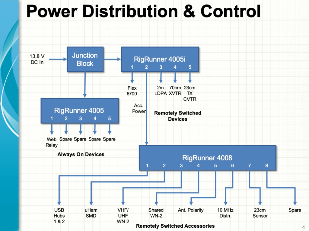
EME Station Block Diagram – Phase 1
The diagram above shows the current configuration of our 2m EME station. As explained in a previous article in this series, we are using a FUNCube Pro+ Dongle with the MAP65 application as our primary JT65b decoder, and we are using our IC-9700 Transceiver along with WSJT-X as a secondary, averaging decoder. Using multiple decoders has proven to be a significant advantage. It is quite common for one of the two applications to decode a weak signal that the other does not.
We use two custom applications (WSJTBridge and Flex-Bridge) to capture the Moon Azimuth and Elevation data generated by the MAP65 application and use it to control the rotators for our EME Antenna Array.
We have been experimenting with Linrad as a front-end to MAP65 and WSJT-X. Currently, we are using the NB/NR functions in MAP65 and our IC-9700 as an alternative to Linrad. We expect the add Linrad into our setup when we add Adaptive Polarity capabilities in Phase 2.

EME Software Operating Environment (click for a larger view)
We use the DXLab Suite for logging and QSL’ing our contacts, along with several web apps to find potential EME contacts and determine the EME Degradation level on any given day.
The screenshot above shows most apps running during a 2m EME operating session.
MAP65 Application – Primary Decoder and Operating Application

MAP65 Software
We are using MAP65 as our primary decoder. It also controls our IC-9700 Transceiver when transmitting JT65b messages. MAP65 used the I/Q data from our FUNCube Pro+ Dongle to detect and decode all signals in the 2m EME sub-band. A waterfall window displays all of the signals on the band as well as a zoomed-in view of the spectrum around the current QSO frequency. MAP65 also generates heading data for our rotators as well as estimates for the Doppler shift between stations. The MAP65 application also provides windows that list all of the stations on the band and the messages they are sending.

EME QSOs via MAP65
The screenshot above shows the main MAP65 window during a QSO with HB9Q. Round trip delay (DT) and signal strength information (dB) are shown for each message that is decoded. The MAP65 application and a manual explaining how to set up and use the program for 2m EME can be downloaded here.
Moon Tracking and Rotator Control

Custom Rotator Control Apps (WSJT-Bridge and FlexBridge)
We developed an application we call FlexBridge some time back as part of our ongoing project to remote our Satellite Ground Station using our Flex-6700-based SDR Remote Operating Gateway. This application includes functionality to operate Az/El rotator controllers based on UDP messages which contain tracking data. We wrote a second application, WSJT-Bridge, which reads the Moon heading data that either MAP65 or WSJT-X generates and sends UDP messages that enable FlexBridge to track the moon. The combination enables MAP65 to control tracking the moon in our setup.
Both of these applications are at an alpha stage, and we will probably separate the rotator control functionality from FlexBridge and make it into a dedicated application.

Antennas On The Moon
One of the first steps in the integration process was to carefully calibrate our rotators to point precisely at the moon. We got the azimuth calibration close using the K1FO Beacon in CT. We made final adjustments visually until our antennas were centered on the moon on a clear night.

EME Tower Camera at Night
We recently installed an additional IP camera which gives us a view of our EME tower. This is a useful capability as it enables us to confirm the operation of our rotator from our shack.
WSJT-X – Secondary Decoder

WSJT-X Software
We also run WSJT-X as a second decoder using the received audio stream from our IC-9700 Transceiver. WSJT-X has more advanced decoding functions and can average several sequences of JT65b 50-second transmissions to improve decoding sensitivity. It only works on one specific frequency at a time, so we use it to complement the broadband decoding capability that MAP65 provides.
We can also transmit using WSJT-X, which enables us to use its Echo Test functionality to confirm that we can receive our own signals off the moon.
The WSJT-X application and a manual explaining how to set up and use the program for EME can be downloaded here.
Finding Contacts and Logging

Finding Contacts and Logging
We use the DXLab Suite for logging and QSL’ing our contacts. DXLab’s Commander application provides the interface between WSJT-X and our IC-9700 Transceiver. This enables the DXLab Suite to determine the current QSO frequency and mode for logging purposes.
MAP65 Software and DXKeeper’s Capture Window
We keep DXKeeper’s Capture Window open on the screen where we run MAP65 so we can easily transfer QSO information to our log as we make contacts.
We also use several web apps to find potential EME contacts and to get an estimate of the level of EME Degradation on any given day:
- WSJT EME Link by NØUK – for 2m EME Sked information
- Degradation in EME signal-to-noise (MMMonVHF) – for estimates of EME Degradation
- LiveCQ – provides automated EME spots from stations running MAP65
We are working on interfacing our instance of MAP65 to LiveCQ so that we can contribute spots when we are operating. More on this to come in a future article in this series.
Next Steps
We have a dual-channel coherent SDR receiver from Afedri in hand, allowing us to do Adaptive Polarity using MAP65. We will be upgrading our station hardware and software to support Adaptive Polarity in the near future.
We are planning some enhancements to our H-Frame to enable better alignment of our antennas along with improved reliability and stability when rotator our antennas. We will cover these enhancements in the next article in this series.
You can read more about our EME station project via the links that follow:
- EME Station 2.0 Part 1 – Goals and Station Design
- EME Station 2.0 Part 2 – Excavation, Footings, and Conduits for New Tower
- EME Station 2.0 Part 3 – Phase Tuned Receive Coax Cables
- EME Station 2.0 Part 4 – New EME Tower Is Up!
- EME Station 2.0 Part 5 – Control Cables and Rotator Controller
- EME Station 2.0 Part 6 – Tower Grounding System
- EME Station 2.0 Part 7 – Building Antennas
- EME Station 2.0 Part 8 – Elevation Rotator Assembly and Sub-System Test
- EME Station 2.0 Part 9 – H-Frame Assembly
- EME Station 2.0 Part 10 – Antennas On The Tower
- EME Station 2.0 Part 11 – Station Hardware in Shack
- EME Station 2.0 Part 13 – H-Frame Enhancements
- EME Station 2.0 Part 14 – New 1.5 Kw Amplifier
If you’d like to learn more about How To Get Started in EME, check out the Nashua Area Radio Society Tech Night on this topic. You can find the EME Tech Night here.
A key part of optimizing our EME Station was to reduce RFI from the network in our home. You can read about the installation of Fiber Optic Networking to reduce RFI and improve our EME station’s performance here.
Fred, AB1OC