Like many memorable events in our lives, our journey towards the Hudson Memorial School ISS Crew Contact began in a modest fashion with a telephone call from Dan Pooler at Hudson Memorial School in Hudson, NH. Dan had been to Space Camp where he heard about an ARISS Crew Contact from … Continue reading Journey to an ISS Crew Contact →
Our project to help the students at Hudson Memorial School in Hudson, NH make contact with an astronaut on the International Space Station via Amateur Radio is a memory now. The link above is an article about the more than year-long journey that led to this once-in-a-lifetime experience. I hope you enjoy it and don’t miss the video of our contact towards the end of the story.
Primary and Backup Stations at Hudson Memorial School
An ISS Crew Contact with Hudson Memorial School will take place tomorrow afternoon. We will be streaming several live video feed from the school all day tomorrow….
All of our gear and Antennas are set up and ready to go. Contact activities will start around 1:15 pm eastern time (18:15 UTC) and our contact will begin at 1:45 pm eastern time (18:45 UTC). The article above contains a link where you can watch the Live Video of the ISS contact. We hope that you’ll join us for the contact!
We have just received word from our ARISS Mentor, Dave Jordan, AA4KN – Our ISS Crew Contact will take place on Friday, December 7th at approximately 1:45 pm EST. Activities on-site will begin with some videos and station tours before the contact.
We will be using the Nashua Area Radio Society callsign, N1FD, for our contact with NA1SS. We believe that our contact will be with Serena Aunon-Chancellor, KG5TMT. We are all very, very excited to hear the news!
Prioritized ISS Passes for our Crew Contact
This date/time was our second choice and the ISS will be on a good pass reaching a maximum elevation of 48 degrees at Time of Closest Approach (TCA). Our contact with the ISS will last about 10 minutes.
Our plan is to begin the final setup of our equipment on Monday, December 3rd at Hudson Memorial School. We will be Live Streaming the setup and testing of our Station at HMS as well as our actual contact via the Nashua Area Radio Society Facebook page.
We are just awaiting notification of the final date and time for our contact and we’ll begin final setup and testing at HMS.
We’ve been sharing our progress as we’ve on the Nashua Area Radio Society’s Youth Forum as we have worked through our final preparations. I also would like to share a summary here along with some insights on what we’ve learned along the way.
An ISS Crew Contact is No Small Undertaking …
Satellite Station 3.0 Antenna System Test
We have been working for almost a year now to get ready for our contact. We’ve built and tested two space ground stations and we’ve discovered and addressed several performance and reliability issues with these stations during trial deployments at Field Day, Ham Fests, License Classes, and during testing here at our QTH.
Leading the ARISS Crew Contact Application Process for our contact
Integration of Radio Space Science concepts into their student curriculum
A Skype contact with a NASA Engineer
Visiting the Boston Museum of Science special exhibit on Space and the International Space Station
A High Altitude Balloon Project with the Nashua Area Radio Society to learn about Atmospheric Science and Space Communications
Space-related student projects including building rovers, participating in an egg drop, and having their pre-engineering program students work on solutions for the ISS
Holding a Field Astronomy and STEM night for students and building Amateur Radio into the school’s annual STEM Nights
Audio-Visual Elements are Important and as Challenging as the Ground Station Equipment…
Sound System Mixer
We planned from the very start to provide a shared, multimedia experience as part of our contact. Our plans included:
Providing a professional-quality audio and video experience for the students, parents, and faculty members at HMS during our contact
Creating a high-quality Video Capture of our Contact
Dave, K1DLM who is a member of NARS had extensive professional sound experience and was able to help us with this part of our project.
Audio System for ISS Contact
Dave put together a professional-level A-V system design to support our contact and provided much of the gear to realize the design. His uses a pair of communications microphones, a pro-mixer, and audio interface gear to provide student and radio audio to the sound system in the auditorium at HMS as well as to an array of video cameras. The system makes extensive use of XLR cabling and pro-level devices to ensure clean audio.
Video Presence on the Internet is an Important Element to Draw Interest in a Project Such as Ours…
We Live Streamed some of our Station Testing activities to Facebook and we were amazed at the interest and response that we received. Many folks worldwide followed our progress on Facebook in real-time as we set up and completed our full station test.
ISS Antenna Camera Test
We are planning to have two IP Video Cameras Live Streaming to Facebook during our contact. One in the room to provide video of the students as they talk with the astronaut on the ISS and a second on our antennas as they track the ISS.
Its Critically Important to Test the Complete Station Ahead Of Time – New Challenges Emerged when we Mixed Audio and Radio Gear…
Full Station Setup and Test
We set up the full station (Primary and Backup) along with all of the Audio and Video Gear about 3 weeks prior to our contact for a complete system test. We learned a great deal in doing this and we encountered several problems which we have since corrected.
On-Air Station Test
The most important issues did not show themselves until we made some contacts with all of the A-V gear in place. We had problems with RF aggravated ground loops in the radio microphone circuits during the initial test. These problems did not show themselves until we added the audio mixer and sound system into the station.
Audio Isolation Transformer
These problems were easily corrected by adding Audio Isolation Transformers into the radio microphone circuits.
XLR Line to Microphone Level Attenuator
We also solved some potential issues related to level differences between line and microphone audio circuits using Audio Attenuators.
These problems were not difficult to solve but they would have seriously degraded our contact if we had not discovered them early while there was still plenty of time to secure parts and retest.
Data Networks in Schools and Public Places Require Configuration Adjustments to Support Contact Elements…
Data Network Test at HMS
Schools and other public places typically do a good job of protecting their data networks and users from threats from both the Internet and within the venue. Tracking Programs, IP Cameras for Live Streaming, and other contact support gear are not typical devices that would be in operation on such networks. Also, many public venues rely almost exclusively on WiFi for access to the Internet and typically prohibit or severely limit client devices from communicating with each other.
WiFi can often suffer from RF interference issues when many devices like Smart Phones are located together in a small area. This situation is common in large gatherings.
Data System for ISS Contact
We had quite a bit of experience with these problems as part of other school projects we’ve done. We worked closely with the IT staff at HMS to plan for and create a network design to support our contact. We opted to use a wired network approach with a local Ethernet switch to implement the IP communications between the elements in our stations and the associated IP Cameras.
The IT team at HMS configured their network to ensure that the IP addresses of our devices were fixed in DHCP and that devices that needed access to the Internet had the access that they required. The IP cameras where the most challenging elements here.
Packed and Ready to Go…
Equipment Packing and Protection
Well, all of our gear is packed and ready to go for setup on-site at HMS. The next article in this series will cover the on-site set up for our contact.
Our planned ISS Crew Contact is almost here! It will take place sometime during the first week of December (December 3rd – 8th) at the Hudson Memorial School (HMS) here in Hudson, NH. I am planning a series of articles here on our blog to explain the process for preparing our ground station(s) and making contact.
The Beginning
Dan Pooler, AC1EN who is a teacher at HMS began this process almost a year ago by reaching out to the Nashua Area Radio Society. Dan wanted to do an ISS Crew Contact at his school and asked if we would help him with the Amateur Radio elements.
We decided early on that we wanted a Direct contact (one which uses an on-site Amateur Radio Ground Station).
Transceiver with 50–100 W output, 1 kHz tuning steps, and 21 memories capable of storing split frequencies
Low-loss coax (such as 9913 or LMR-400)
Mast mounted receive pre-amplifier
14-element yagi antenna with switchable circular polarity
Antenna rotators for azimuth (0–360°) and elevation (0–180°), with an interface for computer control
Computer running tracking software for antenna control (including flip mode operation)
The ARISS approach is to use a series of “secret” uplink frequencies which are determined and provided only to the contact operators before each contact. Doppler correction is not required on the 2m band where the crew contacts take place.
14-element yagi antenna with switchable circular polarity
Satellite Station 2.0 Antenna Details
Our 2.0 Station has an 8-element yagi with fixed polarity. This requirement turned out to have a much more significant impact on the design of the Primary Ground Station than just changing the antenna and ultimately led to the construction of our Portable Satellite Station 3.0. More on this in a minute…
The Backup Station
The backup station requirements are as follows:
Transceiver with 50–100 W output, 1 kHz tuning steps, and 21 memories capable of storing split frequencies
Power amplifier with 100–200W output (optional)
Low-loss coax
Mast mounted receive pre-amplifier
Omnidirectional antenna, either vertical (preferred) or eggbeater style
An uninterruptible power source (UPS or battery)
Our Approach
After consulting with the ARISS folks and some thought, we decided to use the then-current Satellite Station 2.0 as the Backup Station and build a new Satellite Station 3.0 for use as the Primary Station. This approach also involved installing a larger rotator to accommodate the larger antenna and a heavier fiberglass cross-boom. The 3.0 station would also receive a more capable antenna for the 70 cm band and add a 23 cm antenna for a third band.
The plan included upgrading the 2.0 Station Antennas to include switchable polarity and the addition of a 200W power amplifier for 2 m to compensate for the reduced gain of the smaller 8-element yagi in the 2.0 station.
Building The Primary Station
Satellite Station 3.0 Antenna System
The construction and testing of the 3.0 Station are well covered in articles on our Blog, so I’ll just share a little information about the final result. The new antenna system used the same ground-based roof tower arrangement that worked well for the 2.0 station. The larger 3.0 antennas are center mounted on a fiberglass cross boom to prevent the Boom from affecting the antenna patterns. We’ve also added a 23 cm loop yagi for a third band. The 3.0 antenna system also uses a more powerful Azimuth-Elevation Rotator from Alfa-Spid.
2m Yagi Switchable Polarity feed point
The new 2 m and 70 cm antennas use relays at their feed point to enable remote switching of the antenna’s polarity between Left-Hand and Right-Hand circular polarity.
Satellite 3.0 Station Radio and Controls
The upgraded 3.0 ground station adds a control console for switching the polarity of the antennas and a custom-built PPT Router Device to manage PTT sequencing of the radio and the pre-amplifiers at the antennas.
Computer Control via MacDoppler
We continue to use the excellent MacDoppler software to control tracking and Doppler correction in the 3.0 Station.
Building The Backup Station
Upgraded 2.0 Antennas
The upgrades to the 2.0 Antenna System involved the installation of Polarity Switching relays in the feed points of the 2.0 antennas. This upgrade was a fairly straightforward one.
Backup Station Radio and Controls Test
The ground station side was more involved as we needed to build a complete second station. I was able to purchase an Icom IC-910H radio used in good condition for this purpose. The rest of the station components were similar to the Primary Station.
Backup Station Test at the Fall Tech Class
We tested the Backup Station at our Fall Technician License Class, and it worked great! several of our class students used the station to make their first satellite contacts.
I am working on adding a 2 m amplifier and improving the PTT sequencing system on the Backup Station, and I plan to post more about these upgrades here in the near future.
Audio System for Our Contact
Mixing Board at HMS
Our contact will take place in the auditorium at HMS. The room has a high-quality sound system and a mixing board for audio.
Audio System for ISS Contact
Dave, K1DLM, is part of our ISS Crew Contact Team and has quite a bit of pro-level audio experience. He has put together the following plan for our Audio System. His design allows us to smoothly transfer audio to and from the Primary or the Back Stations. We are also planning to record a video and Livestream video to the N1FD Facebook page during our contact, and his design also supports these elements.
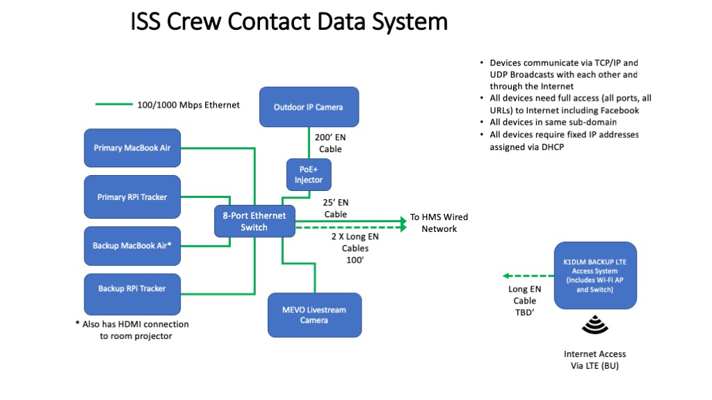
Data System for ISS Contact
The final element in our plan is the Data System. The network at HMS is very tightly controlled from a security point of view, making it difficult to use for contact critical functions like access to up-to-date Keplerian Elements for our straightforward. Dave has an LTE-based Internet Access System that we have used in the past and elected to use to support our stations. We are planning to use the HMS network to transport the Livestream video from our contact. We’ll be using a Mevo Internet Camera for this purpose.
A Million Details…
As you can probably imagine, many details go into making a project like this possible. Here’s a rough timeline of some of the major remaining steps from a Ground Station point of view:
Assemble both stations at our QTH with the 2m amplifier and the final 215′ control cables and feed lines – In progress and should be complete in a few days.
Full Station Test – add the Audio and Data System components and test the full station at our QTH – Within a week.
Configure and Test Data Network Access – for Live Streaming Video and the computers.
Set up Ground Station at HMS and perform Dry Run Test – Complete by December 1st.
Dan and the HMS faculty team are also very busy finalizing the student’s questions and handling press-related activities.
We hope our readers will join us via the Livestream video for our contact. We’ll post more on this as we get closer!
The Nashua Area Radio Society recently held a Tech Night on WSJT-X: FT8, WSPR, MSK144, and More. This Tech Night was recorded and provides a good starting point for folks who want to understand what the WSJT-X software can do, how to use it, and how to integrate it into their station.
August 2018 Tech Night – WSJT-X: FT8, WSPR, MSK144, and More
The video from our Tech Night includes lots of information about how to get started as well as some recorded demonstrations of FT8 and Meteor Scatter contacts.
Topics Cover During WSJT-X Tech Night
Our Tech Night also covered tools like PSKreporter and JTAlert that can be used with WSJT-X. Finally, we spent some time using WSPR to evaluate your station’s performance and how you can use the software to do more “exotic” QSOs such as Meteor Scatter on 6m.
Nashua Area Radio Society members have access to our full library of over 30 Tech Night videos on a wide range of topics for both beginning and advanced Hams. You can see the list of what is available on the Nashua Area Radio Society Tech Night page.
We have established launch windows and begun final launch preparations for our High-Altitude Balloon 4 (HAB-4) launch. We’ve made some modifications to our HAB platform to improve its cold temperature performance and we’ve determined the Balloon and flight path parameters for the upcoming flight. HAB-4 will carry an APRS transmitter and can be tracked using aprs.fi. You can read more about HAB-4 flight preparations via the link that follows.
We have begun looking ahead to Satellite Station 4.0 and where we want to go next after our ARISS crew contact is complete. Our goals for the Satellite Station 4.0 include:
A permanently installed version of our 3.1 Station which can be operated remotely over the Internet
Upgraded Transceivers which add Pan Adapter/Waterfall display capabilities
A more portable version of our 1.1 Station for Grid Square Activations
New 4.0 Station at our Home QTH
The performance of the 3.1 Station’s antennas is very good but the antenna system is a handful to transport. We are planning to install these antennas on a new tower at our QTH and use our Flex-6700 SDR-based Remote Operating Gateway with some upgrades to create a remotely controlled satellite station that can be operated via the Internet. The main components of the 4.0 Station will include:
Upgrade plans for our Transportable station include the addition of remote switchable polarity relays and a new Icom IC-9700 Transceiver when it becomes available.
Polarity Switch Installed in LEO Pack Antennas
The polarity switches have been installed on the M2 Antennas 436CP16 and 2MCP8A antennas in our M2 Antennas LEO Pack. We use a DX Engineering EC-4 console to control the antennas’ LHCP or RHCP polarity selection. We have been doing some testing with the upgraded LEO pack, which includes the polarity switching capabilities, and we are seeing a significant improvement in performance.
AlfaSpid Az-El Rotator
We are also planning to move the upgraded LEO pack antennas to the current 3.1 Tower to take advantage of the AlfaSpid Rotator installed there.
Icom IC-7900 Transceiver
The other major upgrade planned for the 2.2 Station is the new Icom IC-9700 Transceiver when it becomes available. This radio will utilize Icom’s SDR platform and includes a Pan Adapter/Waterfall display which will be a very useful addition for operation with Linear Transponder Satellites.
Upgraded Portable 1.2 Station
We enjoy mountain topping and activating grid squares, so we are planning upgrades to our 1.2 Station for this purpose.
Our 1.2 Portable Satellite Station on Mt. Kearsarge
The 1.2 Station utilizes computer control to enable operation with linear transponder satellites and will use solar/battery power along with a 100w/70w Icom IC-910H Satellite Transceiver.
Solar Panels
A pair of 90W foldable solar panels, an MPPT solar charger, and two LiPo 4S4P A123 batteries provide plenty of power to run the IC-910H Transceiver and the associated computer. The portable station also includes a pair of ARR preamps.
Portable Satellite Antenna System
The antenna system we’ll be using is an Elk Portable Log Periodic 2m/70cm yagi on a camera tripod. Combining a compass and an angle finder gauge helps us correctly point the antenna.
As you can probably tell, all of these upgrades are in progress and at various completion stages. We will post updates here on our Blog as we continue to make progress. Here are links to some of these posts:
It looks like the new IC-9700 is one step closer to being available. It’s now on the Icom website. You can see more, along with the Icom pre-release brochure, on the Icom website here.
This radio will be an excellent choice for Amateur Satellite operations.
The IC-9700 is a new VHF/UHF radio based on the Software Defined Radio (SDR) platform Icom uses in the IC-7300 and IC-7610.
It looks like this is going to be an excellent radio for Satellite, EME, and other weak-signal work on the 2 m, 70 cm, and 23 cm bands. The IC-9700 features a pan adapter display which will be very useful for working contacts through linear satellites.
Based upon previous new Transceivers releases by Icom, I would guess we are at least 8 months to a year away from when this radio will be offered for sale in the USA.
Here’s some video of the forthcoming IC-9700 as well as other gear from Icom. The video also features other new products and updated Firmware capabilities from Icom. Enjoy!
Like many memorable events in our lives, our journey towards the Hudson Memorial School ISS Crew Contact began in a modest fashion with a telephone call from Dan Pooler at Hudson Memorial School in Hudson, NH. Dan had been to Space Camp where he heard about an ARISS Crew Contact from … Continue reading Journey to an ISS Crew Contact →