Nashua Area Radio Society preparations for our upcoming ISS Crew Contact at Hudson Memorial School (HMS) are almost complete. All of our gear is tested and packed, our press release is written, we’ve alterted local news media folks, the students have put together their questions, and have practiced for their contact.

We are just awaiting notification of the final date and time for our contact and we’ll begin final setup and testing at HMS.
We’ve been sharing our progress as we’ve on the Nashua Area Radio Society’s Youth Forum as we have worked through our final preparations. I also would like to share a summary here along with some insights on what we’ve learned along the way.
An ISS Crew Contact is No Small Undertaking …

We have been working for almost a year now to get ready for our contact. We’ve built and tested two space ground stations and we’ve discovered and addressed several performance and reliability issues with these stations during trial deployments at Field Day, Ham Fests, License Classes, and during testing here at our QTH.

Dan, AC1EN and the faculty team at HMS have expended a great deal of effort with the students at their school to prepare for our contact. Their activities have included:
- Leading the ARISS Crew Contact Application Process for our contact
- Integration of Radio Space Science concepts into their student curriculum
- A Skype contact with a NASA Engineer
- Visiting the Boston Museum of Science special exhibit on Space and the International Space Station
- A High Altitude Balloon Project with the Nashua Area Radio Society to learn about Atmospheric Science and Space Communications
- Space-related student projects including building rovers, participating in an egg drop, and having their pre-engineering program students work on solutions for the ISS
- Holding a Field Astronomy and STEM night for students and building Amateur Radio into the school’s annual STEM Nights
Audio-Visual Elements are Important and as Challenging as the Ground Station Equipment…

We planned from the very start to provide a shared, multimedia experience as part of our contact. Our plans included:
- Providing a professional-quality audio and video experience for the students, parents, and faculty members at HMS during our contact
- Creating a high-quality Video Capture of our Contact
- Live Streaming our Contact to Facebook so that more Students, Parents, and the Amateur Radio Community could participate in our contact in real-time
Dave, K1DLM who is a member of NARS had extensive professional sound experience and was able to help us with this part of our project.

Dave put together a professional-level A-V system design to support our contact and provided much of the gear to realize the design. His uses a pair of communications microphones, a pro-mixer, and audio interface gear to provide student and radio audio to the sound system in the auditorium at HMS as well as to an array of video cameras. The system makes extensive use of XLR cabling and pro-level devices to ensure clean audio.
Video Presence on the Internet is an Important Element to Draw Interest in a Project Such as Ours…
We Live Streamed some of our Station Testing activities to Facebook and we were amazed at the interest and response that we received. Many folks worldwide followed our progress on Facebook in real-time as we set up and completed our full station test.

We are planning to have two IP Video Cameras Live Streaming to Facebook during our contact. One in the room to provide video of the students as they talk with the astronaut on the ISS and a second on our antennas as they track the ISS.
Its Critically Important to Test the Complete Station Ahead Of Time – New Challenges Emerged when we Mixed Audio and Radio Gear…

We set up the full station (Primary and Backup) along with all of the Audio and Video Gear about 3 weeks prior to our contact for a complete system test. We learned a great deal in doing this and we encountered several problems which we have since corrected.

The most important issues did not show themselves until we made some contacts with all of the A-V gear in place. We had problems with RF aggravated ground loops in the radio microphone circuits during the initial test. These problems did not show themselves until we added the audio mixer and sound system into the station.

These problems were easily corrected by adding Audio Isolation Transformers into the radio microphone circuits.

We also solved some potential issues related to level differences between line and microphone audio circuits using Audio Attenuators.
These problems were not difficult to solve but they would have seriously degraded our contact if we had not discovered them early while there was still plenty of time to secure parts and retest.
Data Networks in Schools and Public Places Require Configuration Adjustments to Support Contact Elements…

Schools and other public places typically do a good job of protecting their data networks and users from threats from both the Internet and within the venue. Tracking Programs, IP Cameras for Live Streaming, and other contact support gear are not typical devices that would be in operation on such networks. Also, many public venues rely almost exclusively on WiFi for access to the Internet and typically prohibit or severely limit client devices from communicating with each other.
WiFi can often suffer from RF interference issues when many devices like Smart Phones are located together in a small area. This situation is common in large gatherings.

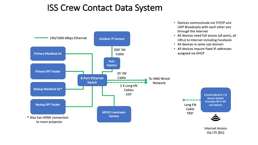
Data System for ISS Contact
We had quite a bit of experience with these problems as part of other school projects we’ve done. We worked closely with the IT staff at HMS to plan for and create a network design to support our contact. We opted to use a wired network approach with a local Ethernet switch to implement the IP communications between the elements in our stations and the associated IP Cameras.
The IT team at HMS configured their network to ensure that the IP addresses of our devices were fixed in DHCP and that devices that needed access to the Internet had the access that they required. The IP cameras where the most challenging elements here.
Packed and Ready to Go…

Well, all of our gear is packed and ready to go for setup on-site at HMS. The next article in this series will cover the on-site set up for our contact.
Fred, AB1OC