2013 Dayton Hamvention

ARRL At Dayton 2013

ARRL At The 2013 Dayton Hamvention

Anita and I had the good fortune to attend the 2013 Hamvention in Dayton, Ohio USA again this year. The Dayton Hamvention covers almost everything Amateur Radio that one can image and it has something for everyone. We’d like to share some of the highlights of this year’s Dayton Hamvention that were of interest to us.

Anita, AB1QB, began her Dayton Hamvention experience by spending a day at Contest University where she gathered some ideas and information to forward her knowledge as a contester. Anita put together a nice summary of what she saw and learned at Contest University which can be viewed here. We spent the following two days looking at all of the exhibits on the main show floor. Our first stop was the ARRL Area. Here we looked at the latest books and publications, dropped off a pile of cards going to the US Bureau, and had a couple of hundred cards checked towards endorsements on our DXCC and WAS awards.

Icon At Dayton

Icom At The Dayton Hamvention

All of the major radio manufacturers (Icom, Yaesu, Kenwood, Ten-Tec and Elecraft) had large displays at the show and they were all packed. One of the more interesting things we saw there was a prototype of Elecraft’s new KXPA100, 100w amplifier for use with the KX3 and other QRP transceivers.

Elecraft KXPA100

Elecraft KXPA100 Amplifier

The unit is a compact and highly portable package and should be a very nice complement to the KX3 for higher power portable operations.

FlexRadio 6700

FlexRadio Flex-6700

We also spent quite a bit of time at the FlexRadio Systems booth. Anita and I have a new Flex-6700 Software Defined Radio on order and we wanted to learn as much about the Flex-6700 as we could. Fortunately, we had a chance to talk with Steve Hicks, VP of Engineering at FlexRadio to gain a much better understanding of the design, architecture and evolution plans for the Flex 6000 series. I expect that this will be one very impressive radio! Unlike previous designs, the 6000 series radios directly sample signals in the RF domain and do all processing and detection of signals digitally. This eliminates the need for roofing and other RF band filtering and allows the radio to operate on multiple frequencies/bands at the same time. The Flex-6700 can implement up to 8 separate receivers simultaneously allowing multiple bands to be monitored. It should also make a great contest radio as its capable of up to SO8V operation. The direct RF sampling approach coupled with the radio’s dynamic range of 140 dB creates a radio that has much lower distortion products and better selectivity that anything else which is currently available. Steve gave an excellent presentation on the architecture of the 6000 series which includes some very good information as part of one of the Forum sessions at the Dayton Hamvention. Creating a new radio and all new software for it is a very large project and it appears that the folks at FlexRadio are almost ready to begin shipping the Flex 6000 series radios. We are hoping to have our Flex-6700 by the end of the summer and we will provide a post here on the new radio once we have it in place in our shack.

Begali Keys At Dayton

Begali Keys At Dayton

As you may know from reading our Blog, I have been working on my CW skills for the past several months. I am beginning to get pretty serious about CW operation and I wanted to get a really good set of paddles. After looking around at many options at Dayton, I decided to purchase a Begali Sculpture Key.

Begali Sculpture Paddles

Begali Sculpture Paddles

Begali makes some of the finest CW keys and paddles in the world. I really like the feel of the Sculpture. It is very solid, heavy and has a very short “throw” during operation. Mr. Begali spent some time with me to show me how to properly setup and maintain my new paddles.

Mr. Begali

Mr. Begali

I cannot wait to get home and get the Sculpture key setup in the shack. It will surely provide more good motivation to continue to improve my CW skills!

DXLab Software Suite

DXLab Software Suite

While a big part of the displays at Dayton are about hardware equipment (radios, antennas, accessories, etc.), I have noticed an increasing trend towards software vendors at Dayton over the last two years. Anita and I have recently switched to the DXLab Suite of software for logging, award tracking, rig control, QSL’ing, etc. DXLab had a nice display at Dayton. We spent some time with Dave Bernstein,  AA6YQ who showed us several features of the DXLab Suite that we did not know about. One cool one was the ability to use Google Earth to plot all kinds of QSO information on a world map. You can see an example of this feature in our Blog by clicking here. Dave also gave an excellent presentation on the DXLab Suite as part of one of the forums at Dayton.

FreeDV Software - HF Digital Voice

FreeDV Software – HF Digital Voice

Another interesting piece of software we saw was FreeDV. This software implements a royalty free codec inside a software program which can be used to send and receive digital voice transmissions on the HF bands. The royalty free codec aspect of this software is a key element as the licensing fees associated with the codecs used by other digital voice systems from Icom, Yaesu, etc. make up a significant portion of the cost of a digital voice enabled radio. The FreeDV folks are also working on a 2M HT which will have their codec built-in. This should be a very interesting product when it comes to market. I plan to try FreeDV in the near future and I am planning a Blog post to share more information about it sometime in the future.

Buddipole At Dayton

Buddipole At Dayton

Anita and I spent quite a bit of time with Chris and Budd Drummond and the gang at Buddipole. Anita and I are big fans of the Buddipole System and we have used it in numerous portable operations including Field Day and a DXpedition to Bora Bora Island in French Polynesia. We heard a lot about various portable operations and DXpeditions that Chris and the gang have done using their portable antenna system. We also talked about some projects that are underway related to yagi’s built using the Buddipole system. Stay tuned for more on this topic in future Blog posts.

Green Heron AZ-EL Rotar Controller

New Green Heron AZ-EL Rotator Controller

The folks at Green Heron Engineering have a new Az-El Rotator Controller in the works which should be very useful for controlling Satellite and EME antenna systems. Green Heron Engineering is also continuing to expand the capabilities of their GH Everywhere remote control hardware and software lineup. We use the Green Heron RT-21D Rotator Controllers in our shack and have been very happy with them.

Piglet  And PigRemote - Remote Control Via iPad

Piglet Remote Control Via iPad

Anita has long been interested in the idea of operating our station remotely via her iPad. We visited Pignology at Dayton to learn about their Piglet and PigRemote devices which enable this sort of operation with the Elecraft KX3 and other radios. We decided to try the PigRemote and we are planning a post on our Blog sometime in the future which shares our experiences with the product.

Yemen DXpedition Presentation

7O6T Yemen DXpedition Presentation

There were also some great Forum Presentations at the Dayton Hamvention and one of our favorites is the DX Forum. We listened to several presentations on recent DXpeditions including the 7O6T Operation in Yemen and the PT0S Operation on St. Peter & Paul Rocks. It is always fun to hear about the planning and work that goes into a DXpedition and these talks were no exception.

We also attended the Top Band Dinner at the Dayton Hamvention where we met some very nice folks and heard some great presentations from a few of the top 160m DX’ers.

All of this  just barely scratches the surface of  what there is to see and learn at the Dayton Hamvention. We hope that you have enjoyed this post and we hope to see you at the Dayton Hamvention sometime in the near future.

– Fred (AB1OC)

QSOs From Our New Station

DXCCs Worked From Our New Station

DXCC Entities Worked From Our New Station (click to view a larger image)

It has been about 11 months since our new station went on the air. In total, we have worked 234 DXCC entities and made over 11,200 QSO from our new station since it went on the air in July of 2012!

A great many of the QSOs from our new station were made as part of various contests that we’ve taken part in including:

We’ve been using DXLab for logging and other station management functions and I learned recently that DXLab can use Google Earth to plot QSOs on a map of the world. For fun, I decided to make a video showing where we have made QSOs using our new station over the last 11 months.

As you can see, a great many of our QSOs have been made to the United States and Europe as part of the various contests that we’ve been in. Anita has worked a number of contacts to Japan and we’ve both worked a good bit of DX around the world as well.

QSOs By Band

QSOs From Our New Station By Band

We have had quite a bit of activity on all of the HF bands and we are looking forward to more fun on 6m, 2m and 70cm as time and conditions permit.

– Fred (AB1OC)

Receive Antenna For The Low Bands Part 1 – Element Layout And Installation

8-Circle Receive Array System Diagram

8-Circle Receive Array System Diagram

Since the completion of our new Station, we have been quite active on the low HF bands (80m and 160m) as well as 40m. We have gotten generally good results from our station on these bands but I have noticed that sometimes DX stations can hear us when we cannot hear them well enough to complete a QSO. This coupled with the high levels of atmospheric and other noise on these bands has led me to decide to install a receive antenna system for use on 160m – 40m. After some research, we choose an 8-Circle Receive Array System from DX Engineering. We chose this system because it offered good performance on the bands we are interested in and could be installed in less space compared to Beverage and other low-band receive antenna systems. As you can see from the picture above, the system uses 8 active vertical elements to form a steerable receive array.

8-Circle Receive Array Directions

8-Circle Receive Array Directions

The eight active vertical antennas are used in various combinations of four at a time to allow the array to be aimed in 8 different directions. The receive direction is set via a controller that is located in our shack.

8-Circle Receive Array Patterns

8-Circle Receive Array Patterns (160m, 80m, and 40m)

The first step in the construction of our Low-Band Receive Array was to carefully read all of the instructions, measure the area where we planned to install the array, and determine the band coverage and sizing. It is also important to place the array at least 1/2 wavelength from any transmitting antennas and away from metal objects and noise sources which could distort the antenna’s patterns or negatively affect its performance. After taking this all into account, we choose to install the array at the front of our property in a wet area which should improve the array’s grounding. We choose to build an array that would cover 160m – 40m and the resulting diameter of the eight active elements was a little over 100 ft which fit in our available space well. The picture above shows that receive patterns on the 160m, 80m and 40m bands (top to bottom) that result from our chosen layout and dimensions. As you can see, the system provides great Front/Back performance on 80m and 40m with a respectable pattern on 160m as well. This should be a good match for our operating patterns.

8-Circle Receive Array Parts

Assembled 8-Circle Receive Array Elements And Grounding Rods

Next, we assembled the eight active receive vertical elements and set them for 160m operation via the internal jumpers. We also took a trip to our local hardware store and purchased lengths of copper tubing and galvanized steel pipe to install the eight vertical elements and the Array Controller. These pipes act as grounds for the receive elements and the controller in the array as well as supporting the elements.

8-Circle Receive Array Construction Tools

8-Circle Receive Array Construction Tools

The construction of the array involved careful measurements to determine the correct location of the array elements. We assembled the needed measuring tapes and hand tools and set about marking the array element locations with stakes.

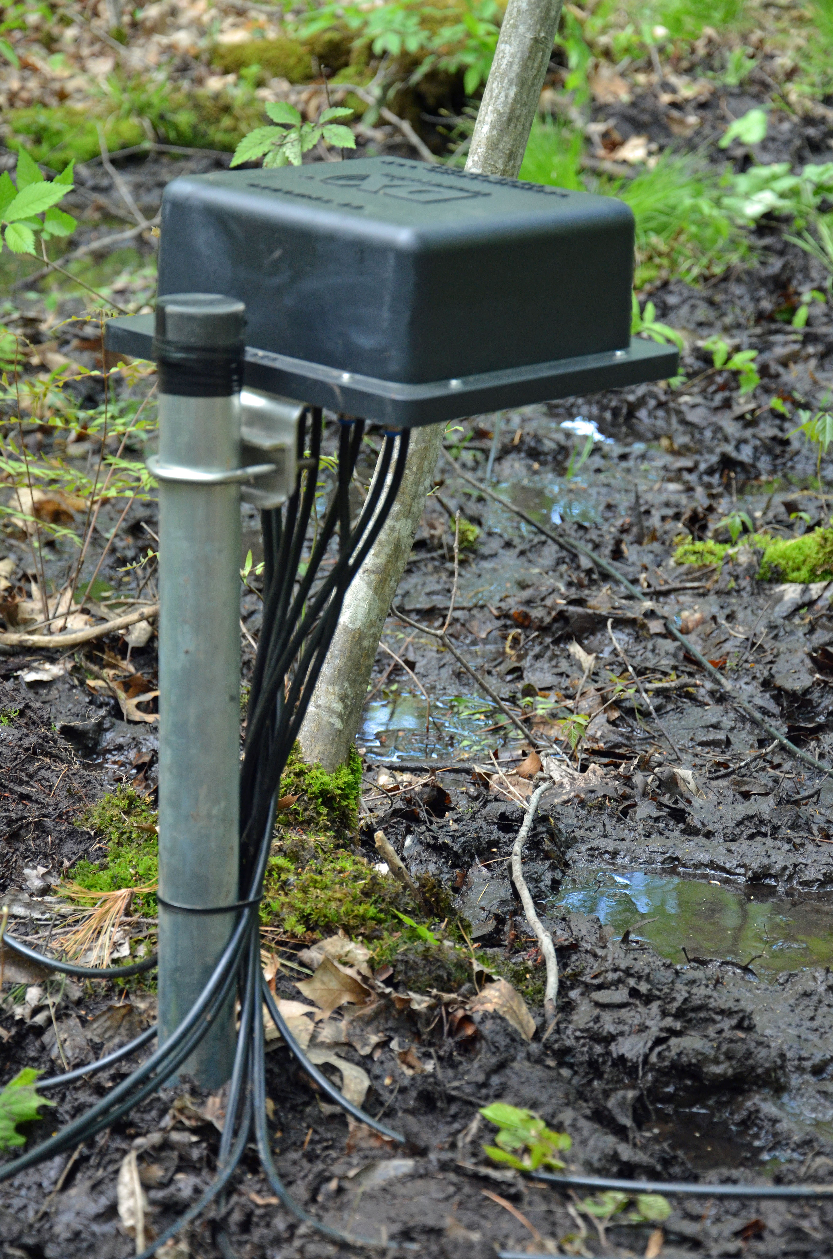
8-Circle Receive Array Control Unit

8-Circle Receive Array Control Unit

With the layout complete, we drove the ground rod for the Receive Array Control Unit at the center of the array layout and installed the control unit. Next, we drove a piece of copper tubing for each of the eight array active vertical elements and installed them. These copper tubing pieces were sunk 4 ft into the wet soil in the area which should provide a good RF ground for the system.

8-Circle Receive Array Vertical Element

Completed 8-Circle Receive Array Vertical Element

The final step in this stage of the installation was to make up eight identical 75-ohm coax cables to connect each of the vertical elements to the Array Control Unit. These lines must be electrically identical to ensure that the elements of the array operate in the proper phase relationships to create the antenna’s patterns. We used Flooded 75 Ohm Coax Cable from DX Engineering to install our Low-Band Receive Array. This coax can be direct buried and will tolerate minor damage to the cable jacket.

At this stage, the most difficult part of our Low-Band Receive Array installation is complete. We need to get some feedline conduits buried in our yard so that we can run the feedline and control cables from our shack to the array. The following are additional posts covering the final steps of the installation, integration, and testing of our new Low-Band Receive Array.

Fred (AB1OC)

AB1QB Enters The 2013 ARRL Rookie Roundup SSB

AB1QB In 2013 ARRL Rookie Roundup SSB

AB1QB In 2013 ARRL Rookie Roundup SSB

Three times a year, the ARRL hosts the Rookie Roundup, in April for SSB, in August for RTTY, and in December for CW. These 6 hour contests are a great opportunity for new operators to get started in contesting. In addition to Rookies, experienced operators are encouraged to be “Elmers” and host new operators, or they can help by just making contacts with the Rookies. A rookie is any operator who was first licensed in the past 3 years.

I have operated seriously in several RTTY contests this year, but have been a little nervous about a serious SSB contest attempt because I don’t have much experience with SSB contacts, except for casually working DXpeditions, and working a pileup or two in Bora Bora with lots of help from Elmer AB1OC.

I thought the Rookie Roundup, on April 21, would be a great introduction to SSB contesting. I started out in search and pounce mode, trying to find rookies and multipliers on the band. In this contest, multipliers are US States and Canadian Provinces, and if you are a rookie, you get 2 points for working other rookies and 1 point for any other contest. The exchange had 4 pieces of information – Callsign, Name, State, and Year Licensed. With N1MM in a RTTY contest. to get the exchange in the log, all you need to do is click on the words/numbers. But for SSB, you need to listen, understand, and type in everything – while giving out your own exchange. This took some getting used to, but by the end of the contest, it became second nature.

I started out on 15m but soon moved to 20m. After determining that search and pounce was not helping my score, I found a frequency and started to run. After a few minutes, I started to get a constant flow of callers, which soon became a pileup! After some initial adjustment, I started to relax and enjoy myself and was able to manage the pileup. The operators in this contest were very friendly and encouraging. I continued to work the pileup for the rest of the contest – almost 6 hours and had a great time!

This has given me the confidence to operate SSB as K2K for the 13 Colonies Event the week of July 4th – I can’t wait!!

By the end of the contest, I had 246 contacts for a score of 11736. Preliminary results are available and I had the top score in Area 1 and the 3rd single op participant overall! I had the most QSOs of any operator – but not as many multipliers. I could have improved my score by moving to 40m toward the end of the contest and trying to work the closer in states in Areas 1, 2, and 3. Those states are difficult to work on the higher bands and represent quite a few multipliers.  The other lesson learned is to use the voice recording capabilities of N1MM for my next SSB contest – after 6 hours of repeating my exchange, I had nearly lost my voice!

All in all this was a great contest and I would recommend it to any new operator.

– Anita (AB1QB)

Up The Tower Again

AB1OC On The Tower

AB1OC On The Tower

Well, our 2m tower-mounted preamp system went on the blink recently so I decided to climb the tower and replace the preamp unit today. The preamp systems for our 2m and 70cm yagis are at the 95 ft level on our tower so the repair involved a climb to the top of the tower.

2m Preamp System

2m Preamp System

The climb took much more time than the repair did. The picture above shows the inside of the 2m preamp housing which holds the preamp itself plus the T/R relay which protects it during high-power transmit operation. A couple of screws and removing and reconnecting the cables were all that was required to change out the faulty preamp.

AB1QB Ground Crew

AB1QB Ground Crew

Anita (AB1QB) helped me as my ground crew on this one and she spent some time in the shack testing the new preamp to ensure that everything was working correctly. After a quick test, we buttoned up the preamp housing and I took a little time to enjoy the view from the top of the tower.

View From The Top

View From The Top

This was my first climb to the top of our tower and it was both exhilarating and tiring at the same time. It’s good to have the preamp working properly again. More fun with EME on 2m is planned for later today when the moon is on the horizon.

– Fred (AB1OC)

Bounce’in Off The Moon…

The Moon

The Moon

This past week has been very productive in terms of 2m Earth-Moon-Earth (EME) QSOs. I’ve continued to use the WSJT Software to make Digital EME QSOs on 2m during both the ascending and descending periods of the Moon. To date, I’ve completed 30 QSOs and worked 16 countries on the 2m band using the Moon as a reflector. The countries and stations I’ve worked include:

  • Australia (VK5APN)
  • Estonia (ES3RF)
  • England (G4SWX)
  • European Russia (R3BM and others)
  • Federal Republic of Germany (DM1CG and others)
  • Finland (OH7PI)
  • Italy (I2FAK)
  • Japan (JE1TNL)
  • Netherlands (PE1L)
  • New Zealand (ZL3TY)
  • Poland (SP4K)
  • Republic of South Korea (HL5QO)
  • Slovenia (S52LM)
  • Sweden (SM5DIC)
  • Ukraine (UT5UAS and others)
  • United States of America (KB8RQ and others)

As you can see from the links to the QRZ pages for some of these stations, many have built fairly sophisticated EME systems.

I2FAK 16x19 EME Array

I2FAK 16×19 EME Array

At this point, I have worked 4 of the 6 continents needed for a Worked All Continents Award via Digital 2m EME. I have set completing and confirming the needed contacts for this award as my next goal. EME contacts are great fun and the EME Ham community has been very helpful to me in getting started.

– Fred (AB1OC)

QSL!

QSL Cards Ready To Mail

QSL Cards Ready To Mail

QSL’ing has often been referred to as the “Final Courtesy of a QSO” and it is certainly a lot of fun to send and receive QSL cards from friends and acquaintances that you’ve made on the air from around the world. QSL’ing is also an important part of qualifying for operating awards which help to hone an operator’s skills as well as encourage test and enhancement of your station. To these ends, I am working towards a variety of operating awards including:

These awards require QSOs to be confirmed using a combination of Logbook of the World (LoTW), QSL Cards, and some via eQSL (AG).

I recently switched to the DXLab Suite of logging and DX’ing programs to facilitate the tracking, QSL’ing, and application tasks associated with these and other awards. DXLab includes a very sophisticated set of features for DX’ing and award tracking. The combination of all of the new QSOs made during the three contests I’ve participated in over the last few months plus the enhanced award tracking features in DXLab resulted in a large number of QSOs that needed to be confirmed. It would be wonderful if all Hams used the online QSL’ing services (LoTW and eQSL) to confirm QSOs but this is far from the case. As a result, I decided to create a batch of  QSL card mailings to try to confirm the needed QSOs.

QSL Label Via DXLab

QSL Label Via DXLab

DXLab has many nice features which can be used to print QSL card labels (or complete cards) and to address the outgoing and return envelopes associated with direct QSL requests. It also provides a tool called Pathfinder to aid in the discovery of QSL routes. These tools were very useful in creating some 400+ direct QSL mailings this past weekend plus another 30+ cards that were sent via the ARRL Outbound QSL Bureau. DXLab also handles online QSL’ing via LoTW and eQSL as well as uploading to ClubLog. It would have been quite a chore indeed to generate all of these cards and mailings without DXLab!

I am very much looking forward to getting cards back from all over the world. It makes checking the mailbox fun!

– Fred (AB1OC)

AB1OC Enters Yet Another Contest – 2013 CQ WPX SSB

N1MM and Related Software

N1MM and Related Software

I am continuing to work the major HF contests to both improve my skills and to work towards a variety of operating awards. My latest effort here was to participate in the recent CQ WPX SSB contest. My schedule did not permit operation during the full contest period but the results were still pretty good. I again used the N1MM logger including its voice keyer features and this was a great aid during contest operations.

Countries Worked During CQ WPX SSB

Countries Worked During 2013 CQ WPX SSB

I was active on all bands 160m – 10m in this contest and was able to work 106 countries – again working a DXCC. The scoring system in CQ WPX SSB favors the lower bands (160m – 40m) so I tried to concentrate there when I could.

AB1OC Claimed Score

AB1OC Claimed Score

My best band overall was 15m where I was able to run during several of the active daytime periods. I am still considered a “rookie” by the rules of this contest, having been licensed for less than three years at this point. Based upon the claimed scores on the 3830scores site, It looks like I may be one of the top “rookies” in my category and will perhaps place in the top 15 in my category overall. The contest also contributed some new prefixes towards the CQ WPX awards that I am working on. Lots of fun as usual.

– Fred (AB1OC)

First Moon Bounce QSO!

The Moon

The Moon

Well, last Wednesday evening was the night. The moon was near Perigee, the sun was not in the way, and my 2m amplifier came back from M2 Antenna Systems and was reinstalled.

2m Amplifier And Sequencers

2m Amplifier And Sequencer

I got everything hooked up and tested before the moon came up that night. Our Earth-Moon-Earth (EME) system consists of an Icom IC-9100 Transceiver and a microHAM MK2R+ for our Sound Card along with a single M2 Systems 2M18XXX Yagi Antenna (18 elements on a 36-foot boom at 112 feet), a tower mounted preamp system from M2, and M2’s EME Sequencers along with their 1.2 Kw 2m amplifier.  For software, we’re using  Joe Taylor’s WSJT Application and the Ham Radio Deluxe Satellite Tracking software to keep our antenna pointed at the moon.

2m EME Setup

2m EME Setup

My first test was to bounce some echoes off the moon just as it came up. With the amp on and set for its rated digital mode output of 900 watts on 2m (it will do 1.2 Kw in SSB mode), I heard my signals coming back from the moon for the first time. The moon was between North America and Europe as it came up, and I noticed several European stations were on 2m EME. After a few CQ calls using JT65B (WSJT mode for 2m EME), S52LM, Milos in Slovenia came back to me, and I successfully completed my first EME QSO on 2m! I also worked two other stations on 2m EME from Europe – DK5SO (in Germany) and UT5UAS (in Ukraine). I suspect some of these folks may have had pretty big EME stations, as their signals were very strong. Here’s a snapshot of my first QSO with S52LM:

EME QSO With WSTJ

EME QSO With WSTJ

As you can see from the snapshot, the round trip delay to the moon and back was between 2 and 2.5 seconds. S52LM’s signal was pretty strong at -23 dB (he was also using close to 1 Kw on his end). At this level, I could not hear anything audible above the noise in my receiver. The following is what the WSJT waterfall looked like:

WSJT EME QSO - Waterfall

WSJT EME QSO – Waterfall

S52LM’s signal is the lines and dots between 0 and 200. These are fairly strong signals by EME standards. The WSJT software’s performance on such weak signals is pretty amazing. (The other lines on the waterfall are weak “birdies”).

Most of the bigger EME stations use an array of long boom yagi’s, so I am pretty lucky to get this done with a single antenna and no elevation rotator. Here’s a picture of a more typical antenna system for EME (this is DK5SO, the station in Germany where I worked):

DK5SO 2m EME Antennas

DK5SO 2m EME Antennas

At this point, I am pretty happy with the performance of our 2m weak signal system.

I heard several stations in Australia a couple of mornings ago before I had my amplifier back. I will try to work them soon. Maybe someday an EME DXCC…. (3 down, 97 to go).

Fred (AB1OC)

Using JT65 On The HF Bands

JT65HF Main Window

JT65HF Main Window

Many of our readers have probably heard about Joe Taylor’s (K1JT) WSJT family of protocols. These protocols were originally developed for Earth-Moon-Earth (EME) or Moon-bounce (via the JT65 variations), Meteor Scatter (via the FSK441 and JT6M variations), Tropo and other very-weak signal communications applications.

All of the WSJT family of protocols and their associated software applications make use of some very sophisticated signal processing techniques to enable communications in extremely weak signal environments. For example, JT65B which is used for EME communications on the 2m band enables communications from the earth to the moon and back using the moon as a (very-poor) reflector. These paths can have 250 dB of loss or more! The JT65 protocol provides about a 10 dB advantage over CW in terms of signal to noise margin on a given path. To help you understand this, using the JT65 protocol to make a contact can provide the equivalent of upgrading the two CW stations using 100W rigs on both ends of a QSO to include a 1 KW amplifier. To understand how the WSJT protocols accomplish this, you can read Joe’s contribution on EME and WSJT that is part of the 2010 ARRL Handbook here.

Joe Taylor’s software is open source and his WSJT family of protocols have been adapted to many applications including their use on the HF bands as well as for Reverse Beacon applications (a.k.a. WSPR). One of these adaptations uses the JT65A variant of the WSJT protocols on the HF bands. This is packaged as part of the JT65HF software from J. C. Large, W6CQZ.

JT65HF can be used to make QSOs on the HF bands at very lower power over long distances using marginal antennas. JT65 QSOs are very simple and only provide the minimum of information exchange to confirm a QSO. The typical sequence (this example has me answering a CQ call from JI1CPN):

  1. CQ JI1CPN PM95         (PM95 is JI1CPN’s grid square, giving his approximate location)
  2. JI1CPN AB1OC FN42  (I respond to the CQ with my call sign and grid square)
  3. AB1OC JI1CPN -12      (JT65HF measures my signal strength for JI1CPN and uses it in his report back to me)
  4. JI1CPN AB1OC R-10   (I give JI1CPN his signal report)
  5. AB1OC JI1CPN RRR   (JI1CPN confirms the we have a good QSO)
  6. TU73 4OVR4 5W         (I confirm the QSO and tell him about my setup)
  7. TU GUY CU 73             (He sends 73 – this is optional)

This is all there is to a JT65HF QSO. The 73 message can be changed to use a limited amount of custom text but that’s it. Each step of a QSO starts at the exact beginning of a minute and takes exactly one minute to complete with 50 seconds used for the transmission of the step and 10 seconds left for the op on the other end to ready a response for transmission. JT65HF automates this sequence so its pretty easy to work through a QSO. If one of the transmissions does not get through to the other end, the other op sends nothing and the sending station repeats the same transmission again until its received correctly. Also note that there is a standard frequency on each HF band where most JT65HF QSOs take place.

Anyone who has setup their station to operate using digital modes already has almost everything needed to use JT65HF. The first additional thing that you need to do is install a precise clock synchronization client on your PC. JT65’s detection algorithms require the transmitting and receiving computers to be synchronized with a fraction of a second. If your PC’s clock is not properly synchronized, you will not get good performance from the decoding software or it may not decode at all. Note that the windows built-in time setting feature IS NOT ACCURATE ENOUGH and you will need to disable it.  You will need a more precise synchronization client which uses the NTP protocol – I suggest the NTP Demon for Windows from Meinberg. Once your clock synchronization is taken care of you will need to download the JT65HF software, install it on your PC (Windows or widows via a virtual environment on the mac, Linux, etc.) and setup the program. There are two simple setup steps.

JT65HF Station Setup

JT65HF Station Setup

The first is your station setup. Here you set your call sign, grid square, and your sound card port. The JT65HF documentation explains how to setup and use the program in detail. One option that you also might set is “Send CW ID with 73…”. This will send your call sign in CW at the end of a QSO for ID purposes.

JT65HF Rig Control/PTT Setup

JT65HF Rig Control/PTT Setup

The other options that you need to set are for Rig Control and PTT. You can use Ham Radio Deluxe, DXLab Commander, OmniRig or the COM port connected to your radio’s CAT interface for these functions.

I think the best way to understand how this all works is to see an actual QSO. The video above shows a JT65HF QSO that I made on 15m with JI1CPN in Japan. I made this contact using only 5w. The video begins with JI1CPN calling CQ. The tones that you hear at the start are his CQ call. I respond to his CQ (note that you can hear my tones but the waterfall does not change while I am transmitting). We then proceed through a JT65 QSO as I outlined it above. Note that I send a custom text message to him at the end giving some information on my antennas and the power level that I used to during the QSO. The video is about 5 minutes long which is the typical amount of time that a JT65HF QSO takes.

I hope that you have found this article interesting and that you might give JT65HF a try. JT65HF is also useful to get on a band where you antennas may not be ideal. There is a pretty good JT65HF community on 160m and its fun to use it to work some DX on this and other HF bands!

Fred (AB1OC)