
8-Circle Receive Array System Diagram
Since the completion of our new Station, we have been quite active on the low HF bands (80m and 160m) as well as 40m. We have gotten generally good results from our station on these bands but I have noticed that sometimes DX stations can hear us when we cannot hear them well enough to complete a QSO. This coupled with the high levels of atmospheric and other noise on these bands has led me to decide to install a receive antenna system for use on 160m – 40m. After some research, we choose an 8-Circle Receive Array System from DX Engineering. We chose this system because it offered good performance on the bands we are interested in and could be installed in less space compared to Beverage and other low-band receive antenna systems. As you can see from the picture above, the system uses 8 active vertical elements to form a steerable receive array.

8-Circle Receive Array Directions
The eight active vertical antennas are used in various combinations of four at a time to allow the array to be aimed in 8 different directions. The receive direction is set via a controller that is located in our shack.

8-Circle Receive Array Patterns (160m, 80m, and 40m)
The first step in the construction of our Low-Band Receive Array was to carefully read all of the instructions, measure the area where we planned to install the array, and determine the band coverage and sizing. It is also important to place the array at least 1/2 wavelength from any transmitting antennas and away from metal objects and noise sources which could distort the antenna’s patterns or negatively affect its performance. After taking this all into account, we choose to install the array at the front of our property in a wet area which should improve the array’s grounding. We choose to build an array that would cover 160m – 40m and the resulting diameter of the eight active elements was a little over 100 ft which fit in our available space well. The picture above shows that receive patterns on the 160m, 80m and 40m bands (top to bottom) that result from our chosen layout and dimensions. As you can see, the system provides great Front/Back performance on 80m and 40m with a respectable pattern on 160m as well. This should be a good match for our operating patterns.

Assembled 8-Circle Receive Array Elements And Grounding Rods
Next, we assembled the eight active receive vertical elements and set them for 160m operation via the internal jumpers. We also took a trip to our local hardware store and purchased lengths of copper tubing and galvanized steel pipe to install the eight vertical elements and the Array Controller. These pipes act as grounds for the receive elements and the controller in the array as well as supporting the elements.

8-Circle Receive Array Construction Tools
The construction of the array involved careful measurements to determine the correct location of the array elements. We assembled the needed measuring tapes and hand tools and set about marking the array element locations with stakes.
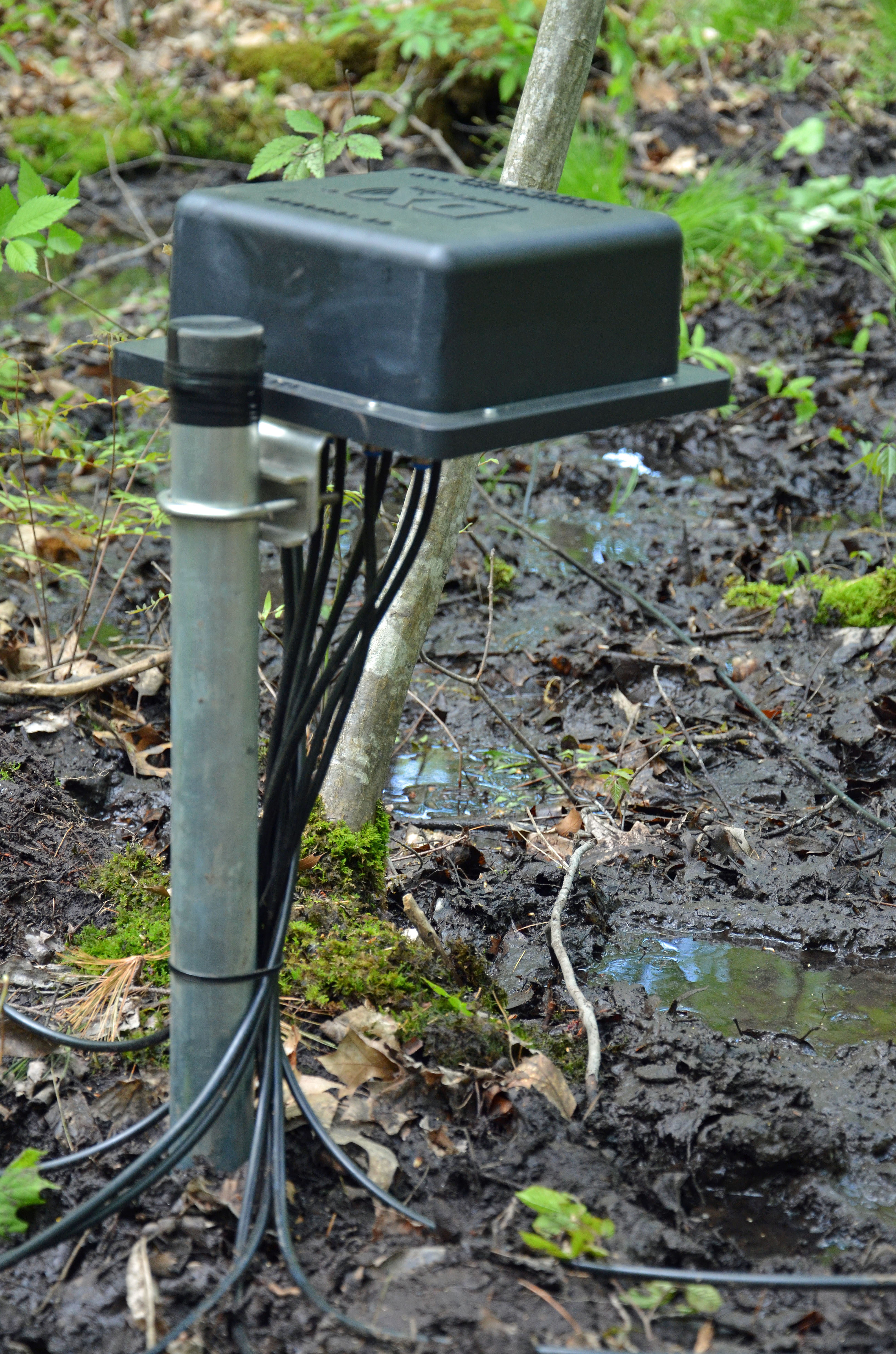
8-Circle Receive Array Control Unit
With the layout complete, we drove the ground rod for the Receive Array Control Unit at the center of the array layout and installed the control unit. Next, we drove a piece of copper tubing for each of the eight array active vertical elements and installed them. These copper tubing pieces were sunk 4 ft into the wet soil in the area which should provide a good RF ground for the system.

Completed 8-Circle Receive Array Vertical Element
The final step in this stage of the installation was to make up eight identical 75-ohm coax cables to connect each of the vertical elements to the Array Control Unit. These lines must be electrically identical to ensure that the elements of the array operate in the proper phase relationships to create the antenna’s patterns. We used Flooded 75 Ohm Coax Cable from DX Engineering to install our Low-Band Receive Array. This coax can be direct buried and will tolerate minor damage to the cable jacket.
At this stage, the most difficult part of our Low-Band Receive Array installation is complete. We need to get some feedline conduits buried in our yard so that we can run the feedline and control cables from our shack to the array. The following are additional posts covering the final steps of the installation, integration, and testing of our new Low-Band Receive Array.
- Part 2 – Second Shack Entry And Ground Point
- Part 3 – Connections To Shack And Final Integration
- Station Automation Part 3 – Antenna Cutover And Final Integration
Fred (AB1OC)
If you have found a spelling error, please, notify us by selecting that text and pressing Ctrl+Enter.
