First QSOs On The 60m Band

60M Band Plan

60m Band Plan (from ARRL Band Plan Chart)

The 60m Band is a relatively new allocation for Amateur Radio Operators in North America. I’ve long wanted to try this band so last evening I took some time to understand what was required and to determine if my available antennas were up to the task. U.S. Amateur Radio operators with a General Class or higher license have secondary privileges on the 60m band. U.S. HAMs can use either USB Phone, CW, or a limited set of digital modes on 60m. The band is “channelized” meaning that one must operate on specific frequencies only. For Phone communications, one must use USB mode only, limit the bandwidth of your signal to 2.8 kHz (most rigs operate USB at a 2.4 kHz bandwidth) and you must set your rig’s frequencies to one of the values shown above corresponding to the five available channels. These same frequencies/channels would be used for digital modes such as PSK31 or RTTY  (see the article on this blog for information on how to get started if your interested in operating using digital modes). For CW operation, you need to set your rig to 1.5 kHz above the frequencies indicated above which will ensure your CW signal is in the center of the associated channel. The highest frequency channel (5403.5 kHz) is shared by HAMs in the U.K. and often provides opportunities to work DX on 60m.

There is an 100W Effective Radiated Power (ERP) limit on this band. See the following page on the ARRL site for information on channel allocations and operating tips. There is also an excellent 60m FAQ page on the ARRL site.

*** Note that this information was taken from the ARRL website and is presumed to be correct for U.S.-based HAMs at the time this article was written. I recommend that  you consult the ARRL website or the equivalent source for license information in your home country prior to operating on 60m to obtain the most up to date operating privileges and rules for the 60m band as they pertain to your home country and license class ***

DXLab Commander 60m Setup

DXLab Commander 60m Setup

Most modern rigs can be tuned to the frequencies used on the 60m band. To make this easy to do and error free, I configured the rig control application in the DXLab Logging Suite which I use to set my transceiver to the correct frequencies, bandwidths and modes corresponding to the five 60m channel allocations for Phone/Digital and CW.

Delta Loop On Tower

75M Delta Loop On Tower

The next step was to determine which of my available transmit antennas would work on the 60m band. After some checking with an antenna analyzer, I determined that the 75m Delta Loop on our tower would tune up well enough to use as a 60m transmit antenna (the feed point for the Delta Loop is on the white fiberglass rod which protrudes to the left of the tower about 15 ft up in the picture above and the apex of the loop is suspended from the upper set of guy cables). I also have a SteppIR BigIR Vertical which will work on 60m but I don’t have that antenna completely installed yet.

The 100W ERP power limit on the 60m band is relative to a Dipole antenna with 100W PEP in. If your antenna has gain relative to a dipole your must adjust your power out accordingly. For example, if your antenna has 3 dBd (3 dB gain relative to a dipole), then you’d be limited to 50W PEP output (50W PEP out + 3 dB gain = 100W ERP). You can use the following link to a handy dB calculator to help you do this calculation if your antenna requires it. Also note that you are required to maintain records based on manufacturer’s antenna gain specifications or equivalent information for your 60m transmit antenna.

8-Circle Low-Bande Receive System

8-Circle Low-Bande Receive System

The Delta Loop also makes a fairly effective receive antenna on 60m. Fortunately, we installed an 8-Circle Directional Receive System for 160m – 40m this past summer and this system works very well as a directional receive antenna on 60m. The 8-circle System has about 10 dB Front to Back performance on the 60m band and is considerably less noisy than the Delta Loop.

I could hardly have picked a better time to begin operating on 60m. It turned out that Canada had just granted 60m privileges to Canadian HAMs on a broad basis on the same day! This will no doubt create many additional opportunities for contacts on the 60m band.  Wikipedia provides an excellent overview of regulatory information associated with the 60m band as well as up to date information on countries which provide 60m band privileges around the world. My very first contact on 60m was a phone QSO with Joe VE3BW in Ontario, Canada. I was also able to work some additional DX including Dragan 9A6W in Croatia, Bo OZ8ABE in Denmark, and Rick, G3XAJ in the U.K. The best part about the 60m band is the relaxed atmosphere I found there. I encountered many HAMs were willing to have a nice conversation and this coupled with surprisingly quiet band conditions made the  15 or so contacts that I have completed to date on 60m a very positive experience.

I’d encourage our readers to give 60m a try. Many antennas such as OCF dipoles, G5RVs, open-wire fed dipoles and long wires will tune up reasonable well on the 60m band and the 100W ERP limit is a good equalizer for small and medium HF stations. I hope to work you on 60m in the near future!

– Fred (AB1OC)

SteppIR BigIR Vertical Antenna Part 1 – Assembly & Installation

SteppIR BigIR Vertical Antenna

SteppIR BigIR Vertical Antenna

When we installed our new tower-based antenna system last year, I was forced to take down our SteppIR BigIR Vertical Antenna to make room for the tower. We really miss having the BigIR Vertical because it provided omnidirectional coverage on all of the HF bands from 80m – 6m and is a good DX antenna due to a vertical antenna’s characteristic low-takeoff angles. The SteppIR BigIR Vertical uses a stepper motor to move a length of beryllium tape up and down inside a hollow tube effectively changing the electrical length of the antenna to tune it. The antenna also has an optional Switchable 80m Loading Coil which allows the antenna to be tuned for the 75/80m band as well. The adjustment of the length of the antenna and the coil is handled by a controller in the shack which reads the frequency of an associated radio and automatically adjusts the antenna as the radio is tuned.

Antenna Layout Plan

Antenna Layout Plan

We decided to re-condition and re-install our SteppIR BigIR Vertical in the woods in front of our house. This location was chosen as it provides adequate separation between the BigIR and our other transmit and receive antennas and is at a high spot on our lot. This area is also surrounded by some fairly wet ground which should enhance the performance of the BigIR Vertical Antenna.

Vertical Antenna Foundation

Vertical Antenna Foundation

The first step in the installation of the antenna was to dig a hole for and pour a concrete foundation for the antenna. All of the needed materials as well as a rental motorized post hole drill were obtained at our local home supply store. We used an 8″ round form and dug down approximately 3 feet into the soil to set the form. We then placed about 6″ of medium stone in the bottom of the hole and filled the form with cement. We set and plumed a piece of 2″ plastic PVC pipe in the center of the form to hold the steel pipe that mounts the BigIR Vertical Antenna.

Foundation And Base Mounting Details

Foundation And Base Mounting Details

The PVC pipe is slotted on the ends with a saw so that it will clamp and hold the BigIR mounting pipe firmly in place with the aid of two stainless steel hose clamps. The mounting pipe that comes with the BigIR is slightly smaller in diameter than the inside of the PVC pipe so a few layers of  electrical tape are used at three points on the mounting pipe to create a good fit. This approach allows the antenna and the associated mounting pipe to be removed from the foundation for use at another site if needed.

Vertical Antenna Radial Plate

Vertical Antenna Radial Plate

The next step in the installation was to assemble and mount a DX Engineering Radial Plate. This Radial Plate is an excellent part and will make it easier to attach the planned 120 radial wires to the antenna. I am using N-connectors on all of the feedline connections associated with our BigIR Vertical so I also installed a N-connector Feed Through Connector on the radial plate to enable easy grounding of the feedline coax’s shield to the radial plate and antenna.

BigIR Pre-Assembly - Element Support Tube (EST) Joint Sealing

BigIR Pre-Assembly – Element Support Tube (EST) Joint Sealing

The next step in the installation was to re-assemble the BigIR Vertical Antenna. The paint on my element housing tubes had faded quite a bit so I lightly sanded them and sprayed them with a couple of coats of Krylon U-V Resistant Clear Coat. This made the tubes look like new and provides protection from fading and weakening of the element tubes due to the effects of UV radiation. SteppIR has made several enhancements to the BigIR since I purchased it a few years back. These include a much better sealing system for the element housing tubes which makes use of heat shrink tubing (pictured above) and a High-Wind Reinforcing Kit for the antenna’s element housing and base. These updated parts and components were obtained from SteppIR for use in re-assembling the antenna. SteppIR has also improved the assembly and instruction manual considerably.

BigIR Wind Reinforcing Kit With Element Housing And Coil

BigIR Wind Reinforcing Kit With Element Housing And Coil

I first connected one end of a spool of 4 conductor control cable to the element housing and reassembled the antenna’s element housing, 80m coil, optional feedline choke balun and the wind reinforcing plate and saddles.

BigIR Pre-Assembly - Base

BigIR Pre-Assembly – Base With Both Sections Of Element Support Tubes

Next, I attached the lower section of the element support tubes to the base assembly. I also prepared the upper section of the element support tube by sealing the joints, attaching the guy rope bracket and installing the top cap/vent and rubber coupler. The antenna is over 30 feet in length when the fully assembled so its best to leave the antenna base/lower element housing tube and the upper element housing tube separated to make transporting the antenna to the site where it will be installed easier.

After transporting the pre-assembled antenna to the installation site, I next attached three lengths of Dacron Antenna Guy Rope to guy rope bracket on the antenna and assembled the two sections of the element support tube to each other, completing the assembly of the antenna.

Coupler UV Protection

Coupler UV Protection

It is a good idea to cover the rubber coupler which attaches the upper and lower element support tube sections together with several layers of electrical tape to protect the rubber coupler from UV damage.

BigIR Installed On Foundation - 80m Coil And Balun

BigIR Installed On Foundation – 80m Coil And Balun

Next I carefully lifted the antenna onto the foundation, attached the three guy ropes to their anchors and then torqued the saddle clamp bolts on the wind reinforcing bracket to 12 ft-lbs. It’s important to not over tighten the saddle clamp bolts as doing so can crack the fiberglass tubes on the antenna. The next step was to tighten the lower rubber coupling clamps, sealing the antenna’s connection to the metal tubing in the foundation.

BigIR Grounding Details

BigIR Grounding Details

The last step in the antenna installation was to connect the ground lug on the 80m coil to the radial plate using a DX Engineering Ground Strap.

BigIR Installed On Foundation - Element Housing And Control Cable

BigIR Installed On Foundation – Element Housing And Control Cable

The picture above shows the element housing side of the installed antenna. The spool of control cable will be covered with a plastic bag to protect it from the weather until the final feedline and control cable connections are run to the shack.

Guy Rope Anchor

Guy Rope Anchor

The picture above shows the details of the guy rope anchors used to secure the guy ropes on the ground. Three Earth Anchors were turned into the soil using a steel rod which provides a solid point to attach the three guy ropes. The rope tension adjusters shown in the picture above were obtained from our local hardware store.

A Stealthy Vertical Antenna In The Woods

A Stealthy Vertical Antenna In The Woods

As you can see from the picture above, the BigIR Vertical is quite stealthy when installed in the woods. While it may not seem so, the work outlined here represents the easy part of a vertical antenna installation. The real work lies in installing the radial wire field around the antenna. The radial field has a significant impact on a vertical antenna’s performance in terms of both radiation efficiency  and takeoff angle. The ground in our area is not very good so I am planning to install an extensive radial field consisting of 120 radial wires, each 110 feet in length. I will cover this part of the project along with the installation of the feedlines and control cables to the shack and the final integration and testing of our BigIR Vertical Antenna System in a future article.

– Fred (AB1OC)

Receive Antenna For The Low Bands Part 3 – Connections To Shack And Final Integration

Antenna Control Stack

Antenna Control Stack

We have completed the final construction and integration of our DX Engineering 8 Circle Receive Array Antenna System for the Low Bands. We built our array to cover 160m, 80m, and 40m some time ago. We also had previously constructed a second entry and grounding system to connect our shack to the new Receive Array System. In this post, I’ll cover the completion of the feedline and control system and the integration of the Receive Array into our shack control systems. The picture above shows the control console for the 8-Circle Receive Array (second box down on the left) as part of the Antenna Control Stack in our shack.

8-Circle Receive Array System Diagram

8-Circle Receive Array System Diagram

The diagram above shows the components in the 8-Circle Receive Array System that we are building. We used all of the components shown above in our installation including the optional Receive Feedline Choke (DXE-RFCC-1) and Receive Preamplifier (DXE-RPA-1).

Array Controller

Array Controller

The first step was to build and install the delay line for the 8-Circle Receive Array System. The delay line ensures proper phasing between the forward and rearward elements in the receive array and is used to create a directional pattern which suppresses noise and unwanted signals from the rear of the array. The delay line is made from a specific length of 75-ohm coax (the same coax that is used in the rest of the system) and is installed in a coil next to the Array Controller. We also terminated the control cable on Array Controller. The control cable carries 12V power for all of the active electronics in the array (12V, 250 ma) and the selection of the control cable must account for the potential voltage drop between the shack and the Array Controller. Our cabling is quite long (approximately 500 ft) so we choose a Heavy Duty Control Cable (DXE-CW8-HD) from DX Engineering. We paralleled spare pairs in the cable with the 16 ga. power and ground wires to ensure that we did not have a significant voltage drop in the control cable.

Feedline Choke

Receive Feedline Choke

The next step was to run a length of 75-ohm coax from the Array Controller to the shack entry point. We choose to install a Receive Feedline Choke in the feedline due to its long length and its installation on the ground (as opposed to buried which would have been impossible in our woods due to roots and rocks). The choke prevents the shield on the feedline from conducting signals from local noise sources or AM radio stations nearby. These problems, if not corrected, would distort the directional pattern of the Receive Array and create higher noise levels in the system. The choke needs to be installed 20-30 ft from the edge of the 8-Circle Receive Array in the feedline. The unit requires a good ground so we mounted it on a 5/8″ x 8 ft ground rod which we drove into the soil. We used a pair of standard ground rod clamps to mount the Receive Feedline Choke on the ground rod. We then secured the feedline and control cables to the ground every 6 ft or so using Metal Anchor Pins from DX Engineering.

Shack Entry Termination

Shack Entry Termination

Once we got the feedline and control cables near the house, pulled them through the PVC conduit we installed to get them across our yard and to the shack entry point. We then terminated them on the ground system and static suppressors that are explained in the article on the construction of our second shack entry system.

Completed Shack Entry

Completed Shack Entry

Finally, we ran the feedline and control cables into the house and to our shack.

DXE Sequencer

DX Engineering Time Variable Sequencer Unit

We use high power on the low bands (1 KW) so the Receive Array’s active electronics must be powered down and the elements grounded when we are transmitting. The Array Controller handles these steps when power is removed from the control cable to the array. To allow for safe switchover of the array between receive and transmit, the power must be removed from the array a few milliseconds before our transmitters and amplifiers switch to transmit. These steps are accomplished via a Sequencer. In a single radio system, a DX Engineering Time Variable Sequencer Unit (shown above) would handle this job including the required time sequenced keying of an associated transceiver and amplifier.

microHAM MK2R+

microHAM MK2R+

Our shack has a total of four transceivers configured as two SO2R operating positions so we used our microHAM MK2R+ SO2R Controller (the unit on top of our Icom IC-9100 Transceiver in the picture above) to control the overall sequencing of our transceivers and amplifiers and the DX Engineering Sequencer to provide fast switching of the power to the Receive Array under control of the MK2R+.

Receive Array Controller

Receive Array Controller

The DX Engineering Sequencer is the last element in the control cable before it terminates on the Receive Array Control unit (shown above). This device uses a rotary switch to control the selection of one of 8 directions that the Receive Array, can be electronically pointed in.

DXE Receive Preamp

DXE Receive Preamp

Due to the length of our feedline, we choose to install a Receive Preamp in the feedline. This unit is installed close to the radio and is powered from the shack’s 13.8V power supply.

75 Ohm To 50 Ohm Transformer

75 Ohm To 50 Ohm Transformer

The final element in the feedline is a 75-ohm to 50-ohm transformer from Wilson Electronics, which converts the 75-ohm feedline from the Receive Array to the 50-ohm impedance at the antenna terminals on our Icom IC-7800. The IC-7800 has a provision to use a separate Receive Antenna, and we configured it to do this by default on the 160m and 80m bands.

With everything in place, we began by testing the Receive Array system with our Transceiver set at a low power level (10 w). Once we verified the operation of the Sequencing System, we turned on the amplifier and verified proper operation a high power. The setup worked perfectly, and the receive Array is much quieter on 160m and 80m than our transmit antennas. This enables one to “hear” weaker signals on these bands much better. The array is also noticeably directional, as expected. I am anxious to operate on the low bands a few evenings (and early mornings) to see how well the system performs, but the early indications are very good.

The following are additional posts covering the other parts of the installation, integration, and testing of our new Low-Band Receive Array.

Fred, AB1OC

Receive Antenna For The Low Bands Part 2 – Second Shack Entry And Ground Point

Antenna Layout Plan

Antenna Layout Plan

When I began construction of a dedicated 8-Circle Receive Array antenna system for the low bands (160m – 40m) some time ago (see part one in this series for details), I knew that I’d have to locate the new antenna system as far away from my tower and other transmitting antennas as possible to avoid overloading, pattern distortion and pickup of re-radiated noise by the new receive system. The picture above shows the antenna layout plan that I have been building to for some time now. My tower is in back of the house and the Low Band Receive Array System from DX Engineering that I am building is at the very front of our property. This provides the maximum separation between it and the transmitting antennas. The final element of my antenna build plan is to re-install our SteppIR BigIR Vertical Antenna at the side corner of our lot to separate it from the other antennas as well.

Second Shack Entry And Ground Point

Second Shack Entry And Ground Point

Placing antennas on the other side of our house required me to build a second shack entry and grounding point. The picture above shows the new entry point ready to accept feedlines and control cables. The first step in its construction was to install 3″ PVC conduits to get the feedlines from the woods in front of our house to the shack entry point and then through the outside of the house.

Grounding System Overview

Grounding System Overview

The next step was to construct the grounding system for the entry point. I again used one of the excellent Ground Bar Kits from Storm Copper. This was attached to the side of my house and it will provide grounding for the feedline for the SteppIR BigIR Vertical Antenna when it is re-installed. I installed a PolyPhaser Static Coax Lightening Protector on the Storm Ground Bar so that you can see how that element is mounted on the Ground Bar.

Grounding System Details

Grounding System Details

It is very important to have a good single point earth ground to provide lightning protection and a path for static electricity build up on your antennas to sink to the ground. I used a standard 5/8″ x 8 ft electrical ground rod driven into the soil about 7 ft to provide the earth ground for my second shack entry point. This ground rod is connected to the Storm Ground Bar via a heavy ground cable (right side of the ground rod) and a crimp-on lug. The heavy copper ground cable to the left of the rod bonds the second shack entry ground to our electrical service entrance ground and to the tower and antenna grounding systems at the back of our house. This cable runs around the outside perimeter of our house and terminates on an 8 ft electrical ground rod approximately every 10 ft. The bare copper bonding cable is also buried a few inches in the soil which hides it and lowers the system’s resistance to ground somewhat. Note the use of clamps and a crimped lug to make all of the connections in the pictures above. Using mechanical connections of these types is essential and you should never solder ground connections as a lightning hit will instantly vaporize soldered connections. The resulting interruption of the connection to ground is very dangerous.

My Low Band Receive System uses a 75-ohm feedline and thus requires a 75-ohm Coaxial Lightning Protector which I got from DX Engineering. I also needed a means to provide static suppression for the control lines to the Receive System and to my BigIR Vertical. I used a Copper Ground Rod Clamp from Alpha-Delta to attach these items directly to the ground rod at the entry point. This required some minor modifications to the mounting brackets for the 75-ohm static suppressor and the Control Line Static Suppressor from ArraySolutions. Stainless steel hardware was used to fasten everything together to complete the installation. The resulting system worked out quite well is ready to accept the feedline and control cable from the receiving system which I hope to complete this coming weekend.

The following are additional posts covering other parts of the installation, integration, and testing of our new Low-Band Receive Array.

Fred (AB1OC)

A First Antenna For HF Use

OCF Dipole And Ground Plane Antennas On A Push-Up Mast

OCF Dipole And Ground Plane Antennas On A Push-Up Mast

I am often asked, “what is a good first antenna for use on the HF bands”. This is a difficult question to answer and there is no one answer which is best for everyone who asks this question. For example, a HAM in a restricted HOA situation will have a much more limited set of choices than a HAM with a small lot and some trees. The restricted HOA situation is often a very difficult one and is usually best solved with an HF antenna such as a Buddipole that can be put and taken down easily. For this post, I am going to concentrate on some choices for HAMs with a small lot and perhaps a few trees. The picture above shows my first real HF antenna system (it also included a VHF/UHF ground plane antenna for 2m and 70cm repeater access).

In my mind, the best HF antenna for a new HAM should have the following characteristics:

  • It should be inexpensive
  • It should be relatively easy to put up
  • It should be somewhat stealthy so as to be neighbor and XYL/OM friendly
  • It should handle at least 100w of continuous power (I think the new HAM does best with this level of power as it provides more breathing room while the operating technique is being learned)
  • At a minimum, it should cover the 20m band and ideally should also cover 40m as well as some of the higher frequency HF bands (I consider 20m to be the most important HF band for the beginning HAM as it allows working both DX and domestic contacts, has many big guns which will be easier for the little pistol HAM to work and is of a manageable size)
  • It should be reliable and stay up year-round without a lot of maintenance

*** DISCLAIMER – The author assumes no liability, warranty or responsibility for the safety, possible injury, reliability or function of the antenna installation methods, materials, techniques and systems discussed in this post or anywhere else in this Blog or for any injury or consequential losses, injury or damages resulting from or incurred in connection with the use of the information presented here. Antenna work is potentially dangerous and can result in serious injury or even death. These ideas worked for me but may not work for you. You decide to use the ideas suggested here you do so entirely at your own risk. ***

I am going to talk about two different antenna systems that will meet these goals – an Off-Center Fed (OCF) Dipole and a Vertical Dipole. Some might say that vertical antennas should be on this list as well but I find them to be more complex to install properly and therefore are not, in my estimation, the best first antenna for a new HF operator.

My first antenna was an OCF Dipole from Buckmaster which covers 80m – 10m (15m excepted). This antenna is a good performer and I was able to work and confirm about 125 countries on multiple bands with it. This antenna is very well made and I still use it for domestic contacts and some DX at my QTH. The OCF dipole is a multi-band wire antenna that does not use traps and is a relatively simple install.

Buckmaster OCF Dipole Installation Diagram (Courtesy Buckmaster)

Buckmaster OCF Dipole Installation Diagram (Courtesy Buckmaster)

The OCF dipole is usually installed in an inverted-V configuration so the ends do not need to be very high off the ground (~10 ft is good). The center should be 35 – 45 ft up and must have a reasonably solid mounting point to support the weight of the center matching balun and feedline. The best approach is to suspend the balun/feedline combination from a tree limb if one is available in the right location.

Guying Arrangement Looking Up The Mast

Guying Arrangement Looking Up The Mast

In my situation, I did not have a suitable tree in the correct location so I installed a 50 ft heavy-duty fiberglass push-up mast (only extended to 42 ft – see below for details) on the side of my house to provide the needed center support. The push-up mast came from Max-Gain Systems, Inc.

Mast Guy Anchor On Ground

Mast Guy Anchor On Ground

As you can see from the photo above, the mast is guyed at two levels with a 3-point guying system made from 0.188″ synthetic rope from DX Engineering. One pair of the guy ropes is anchored on the ground using a large, screw-in earth anchor from DX Engineering.

Mast Guy Anchor On House

Mast Guy Anchor On House

The other two sets of guy ropes are attached under the eves of my house using sturdy anchors built from 2″x6″ and 2″x4″ pressure-treated lumber. NOTE THAT ALL OF THE ANCHORS MUST BE SOLIDLY MOUNTED IN THE GROUND OR ATTACHED TO STUDS IN THE HOUSE STRUCTURE. I cannot stress enough how important it is to ensure that guy attaching points are solid and will hold up. A mast of the type shown here will not be stable without proper guy ropes and anchors and it will collapse if the guy system is inadequate or if it fails. I used a 50 ft mast but did not extend the top section very much (only a foot or so to mount the balun for a total height of about 42 ft) to ensure that there was a sold mount for my antennas (note that the top guy attaching ring from MGS is just below the point there the OCF dipole’s balun attaches to the mast with two stainless steel hose clamps – this ensures a stable mounting point for the balun).

Push-Up Mast Anchor To House

Push-Up Mast Anchor To House

The mast is fastened to the house about 18 ft up from the ground with a block and a piece of galvanized strapping material that is securely fastened to the framing of the house with lag bolts. Once the antenna’s balun and feedline are installed on the top of the mast and the guy ropes are in place, the mast can be pushed up into position with the help of three helpers – one on each pair of guy lines. The helpers are essential to ensure that the guy ropes can be maintained with enough tension to provide support for the mast and to keep it stable as it is pushed up. The feedlines (I used LMR-400 UltraFlex coax) are taped to the mast every few feet as the mast is pushed up.

Mast Section Locking Clamp

Mast Section Locking Clamp

The MGS mast has plastic clamps to lock each section of the mast in place as it is pushed up. I have found that after continuous exposure to the sun and the elements, these clamps can break if they are made tight enough to hold the mast locked over long periods of time. To solve this problem, I install a stainless steel hose clamp at each mast section joint after the section is pushed up to its extended position. This locks the section securely without requiring excessive tension on the plastic locking collars.

Feedline Conduit At Base Of Mast

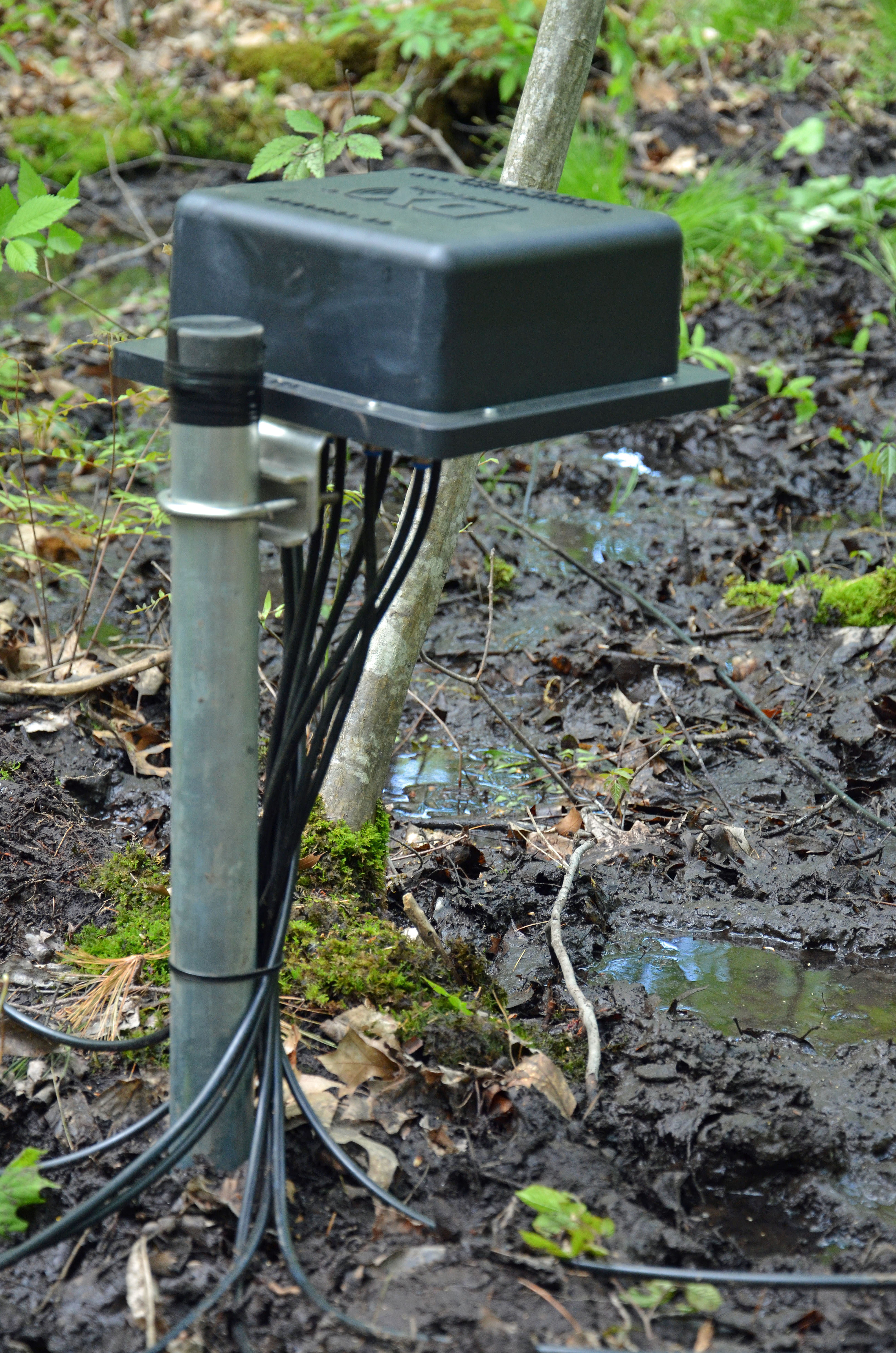
Mast Base And Feedline Conduit

It’s also important that the base of the mast has a solid point to rest on and not be able to move around. To accomplish this, I made a base out of several heavy 2″x8″ sections of pressure-treated lumber. The upper piece of 2″x8″ lumber is drilled with a hole saw to provide a hole for the mast to sit firmly in and the blocks are held in place on the ground with several large galvanized 18″ spikes. I also opted to install plastic conduits in the ground to route my feedline from the base of the antenna to the entrance of my shack. The feedline is also connected to a well-built earth ground via an Alpha-Delta surge projector prior to entering the shack. I also strongly suggest disconnecting your feedlines prior to them entering your house during times of potential lightning activity or when your station is not in use.

Antenna Feed Point Connection Details

Antenna Feed Point Connection Details

The last area to note is the proper way to install the feedline where it attaches to the antenna. You are trying to accomplish two things here – first, to provide a drip loop so that water does not run down your coax and second to provide a means to create a high impedance choke to block any RF that might flow on the outside of your feedline. The later is not a big problem with the Buckmaster OCF dipole as it uses a high-quality balun for matching and decoupling at the feed-point. It’s also important to seal the connections between the antenna and the feedline at the connectors. To do this, I use a combination of CoaxWrap and Super 88 Electrical Tape (wrap the connection and connector shell with one layer of electrical tape first, then a layer of CoaxWrap, then a final layer of electrical tape for protection). The upper antenna in the picture is a Diamond X-300NA ground plane vertical antenna that I have installed on my mast for accessing local 2m and 70cm repeaters.

Dipole Antenna End Anchor

Dipole Antenna End Anchor

Once the center of the OCF Dipole is up and the feedline supported, one needs to anchor the two ends. I used a couple of pulley’s attached to two sturdy trees near the ends of my antenna. I used the same synthetic rope attached to the insulators on the ends of the OCF Dipole to provide support for the ends of the antenna. Note the use of rubber tarp stretchers to provide tension on the support ropes. I have found that this system works quite well and keeps the antenna supported without breaking or excessive sagging as the trees sway with the wind. You do not need to make the end supports extremely taut – a little bit of sag in the antenna wire is OK and a slight amount of slack will reduce the stress on your antenna in the wind.

The only maintenance required with this sort of antenna is to inspect the coax and adjust the tension on the guy ropes and end supports periodically. I do this simple maintenance twice a year in the fall and in the spring.

20M Vertical Dipole - A Stealth Antenna For DX Work

20m Vertical Dipole – A Stealth Antenna For DX Work

Can you find the antenna in this picture? It’s a 20m vertical dipole located just to the right of the tree at the center of the picture. This is one of the simplest and least expensive HF antennas to install, is stealthy and it works very well. Its radiation pattern exhibits a low takeoff angle which makes it an excellent choice for DX work and it will exhibit a reasonably low SWR across the entire 20m band. All you need to build this antenna is an inexpensive 20m dipole antenna, some rope and a tree limb that is about 38 feet or so from the ground.

Vertical Dipole Anchors At Base

Vertical Dipole Anchors At Base

Instead of installing the dipole horizontally, you install it vertically with one end about 2-3 ft off the ground using a rope (ideally with a pulley) to support the other end from a tree limb. about 40′ up. Note the use of the rubber tarp stretchers to maintain a modest amount of tension on the ropes attached to the ends of the dipole.

Vertical Dipole Anchor At Antenna Feedpoint

Vertical Dipole Anchor At Antenna Feed-point

Before pulling the antenna up, attach a suitable length of lightweight feedline (RG8X coax cable works well) to the feed-point of the dipole. Don’t forget to seal the connection with a combination of CoaxWrap and Electrical Tape. You will also want to attach a piece of synthetic rope at the feed-point at well. Once the antenna is pulled up into position, anchor the feedline to the ground so that it slopes away from the antenna’s vertical section at approximately 45 degrees. Then fasten the feed-point rope to the ground opposite the feedline so that it pulls the vertical section of the antenna straight (without the feed-point rope, the weight of the feedline and the 1:1 balun at the feed-point will prevent the antenna from being a straight, vertical radiator). As explained with the OCF Dipole previously, it is important to properly ground the feedline before it enters your house and to disconnect the feedline when lightning might be present and when your station is not in use.

As with the OCF dipole, this antenna’s feedlines and support ropes should be checked and adjusted twice a year. Given this is such an effective and simple antenna, you might ask “why not always use a vertical dipole”? The biggest drawback is that it only will work on a single band. It’s also difficult to put up one of these for 40m (you’d need a tree limb about 70 ft high and a safe way to get a rope over it). Some hams do put several vertical dipoles up at different spots on their property and this makes an excellent and simple multi-band antenna system.

I hope that this post provides some useful ideas for HAMs contemplating the installation of their first HF antenna. As noted by Rick (W1RAG), a combination of an 80m – 10m OCF Dipole and a 15m Vertical Dipole would cover almost all of the HAM bands including the WARC bands (Rick uses this combination of antennas at his QTH).

My final advice is to be very careful when installing antennas to keep yourself, ladders, antennas, and feedlines away from power lines and take extra care when using ladders and when working at heights above the ground. It is usually best to rent the services and expertise of a bucket truck and operator to install the supports on trees rather than trying to use a ladder or climb yourself. This has the added advantage that proper attachments and pulleys can be easily and properly installed safely. I have used the services of a professional bucket truck and operator several times on projects like these and I have never been sorry about the modest cost involved.

– Fred (AB1OC)

Mobile HF Installation – Part 1/4 (Initial Installation)

Mobile Installation In Ford F-150

Mobile Installation In Ford F-150

We have been planning to install a mobile HF setup in one of our vehicles for some time now. Our car and truck currently have an Icom IC-2820h 2m/70cm DSTAR transceivers installed in them, providing access to our local repeaters. We also purchased a backup Icom IC-7000 Transceiver some time ago with the intention of installing it in one of our vehicles. Our planning for our Mobile HF setup involved talking to Ron Douglass at Scorpion Antennas and studying the excellent K0BG Mobile HF website. I’ve settled on the following components for our Mobile HF installation in our 2009 Ford F-150 truck:

This is quite a complex mobile installation – especially the amplifier plan. Given that I have limited experience with mobile HF, I am planning to complete the project in phases:

This past weekend, we completed Phase 1 of the project – installing the IC-7000 Transceiver and a HAMStick Antenna in our F-150 Ford Truck.

Icom IC-7000 Control Head

Icom IC-7000 Control Head

The first step in the installation was to determine a good location for the IC-7000’s Control Head. It’s important to read the radio’s display and access its controls without taking one’s eye off the road. It’s also important to mount the unit so that it will not block the view of the road. After trying several locations while seated in the vehicle, I settled on a mounting location just below the top of the dash and just to the right of the steering wheel. This put the control head right in front of the driver in an easy-to-read and reach location.

Icom IC-7000 Head Unit Mounting Bracket

Icom IC-7000 Control Head Mounting Bracket

I made a small bracket from some sheet aluminum which was attached to the underside of the dash pad with three screws. The bracket provides a secure mount for the Icom MB-105 Mobile Mounting Bracket for the IC-7000’s Control Head.

Icom IC-7000 Radio Mounting

Icom IC-7000 Main Unit Mounting

The next step was to mount the IC-7000 Main Unit. I mounted it on the right side of the front passenger area on the lower kick panel. I mounted the radio with the rear panel facing the passenger so that we could connect control and data cables to allow the passenger to operate using digital modes or connect a PC for automatic logging. This approach also makes working on the antenna, power, and other radio connections possible without removing the radio from its MB-62 Mounting Bracket. I removed the feet and handle on the radio, which allowed me to mount it closer to the kick panel, which helped keep the unit out of the passenger’s feet. At this point, I ran the radio’s power cable through a wire grommet in the firewall and connected the fused power leads directly to the battery. I also used Icom’s OPC-1443 Separation Cable to connect the radio to the control head mounted on the dash. The final part of mounting the radio was to run an audio cable from the radio to the auxiliary audio input on my truck’s sound system, allowing me to use the truck’s audio system and speakers to amplify to radio’s audio.

Mobile Antenna Farm

Mobile Antenna Farm (HAMStick Is Center Antenna)

The final step of the installation was to install the MFJ HAMStick Antenna and mount. As you can see from the picture above, I choose to install the HAMStick on the roof of the truck. This approach works well because it allows the metal surface of the truck to act as the best possible ground plane for the mobile HF antenna.

HAMStick Magnetic Mount

HAMStick Magnetic Mount

I used an MFJ-336T Tri-magnet Base to mount the HAMStick. This base is solid and does not allow the antenna to move around on the vehicle. It was also a good choice as I plan to replace the HAMStick with the Scorpion Screwdriver Antenna later in the project. It was easy to route the antenna’s coax feedline through the corner of the door and then conceal it behind the trim panels in the interior of the truck as it was routed to the IC-7000’s base unit. The HAMStick antenna uses a spiral-loaded fiberglass section which includes a loading coil and a stainless steel whip on top.

20m HAMStick SWR

20m HAMStick SWR

The resonant frequency of a HAMStick is adjusted by changing the length of the stainless whip at the top of the antenna. As you can see from the picture above, I used our RigExpert AA-54 Antenna Analyzer to adjust our 20m HAMStick to favor the phone side of the 20m band. This tune-up will also allow operation in the 20m digital sub-band as well as in all but the very bottom of the 20m CW sub-band. We also purchased a 40m HAMStick. The bandwidth of the 40m HAMStick is limited due to its short length on 40m, so I tuned it to work best in the 40m DX window and the lower part of the US phone sub-band on 40m.

Mobile HF Log

Mobile HF Log

The last step in the installation was to secure a paper log and band plan to the truck’s center console using some large rubber bands. I use the paper log along with a small spiral-bound notepad to note information about my QSOs when operating mobile. The information on the notepad is transferred to the paper log when I am stationary.

With the installation complete and the 20m HAMStick installed, I made my first QSO with Ken (G0KEN) in the U.K.! The signal reports were 57 both ways, and we had a nice QSO on 20m. I do have some ignition noise when my truck is running, but the combination of the IC-7000’s excellent Noise Blanker and DSP Noise Reduction features reduced the noise level to S3 or less. I took my truck for a test drive with the new radio and worked a Special Event Station (OO7VA) in Belgium and several United States stations. All in all, our initial Mobile HF installation seems to be working quite well. The next step is to work on grounding the various parts of my truck and add some RF choking material to the power and other radio connections to try to lower the noise levels. This will be the topic of Part 2 of this series of posts.

– Fred (AB1OC)

2013 Field Day

CW Station Operations

CW Station Operations

Our club, PART of Westford, MA USA, held our 2013 Field Day event at the Concord Rod & Gun Club again this year. We operated three HF Stations (SSB Phone, CW, and Digital) as well as a VHF and a Satellite Station this year. All of our operations were QRP 5 watts and used solar/battery power. The photo above shows Bob (W1IS) and Bill (AA1O) operating the CW station. Our day began with the setup of our antennas and the four stations.

Field Day Tri-Bander

Field Day Tri-Bander

Anita (AB1QB) and I handled the HF beam antennas for our Field Day Operation. This included a Hy-Gain TH-3JRS Tri-Bander loaned to the club by Allison (KB1GMX) which was installed 20 ft up on a guyed military push-up mast.

15m Buddi-Beam

15m Buddi-Beam

We also brought our 15m and 10m 3 element budi-beam mono band yagis which we designed for portable operations. These antennas plus a G5RV and a 40m wire beam made up our HF antenna farm for Field Day. All of these antennas were brought to a common interconnect panel where they could be connected to any of the three HF stations. We setup all of these antennas at home the week before to confirm that they worked as expected and to ensure that they could be erected safely and quickly at our Field Day site.

VHF Tower

VHF Tower

Another part of our team spent time to put up a Rohn 25G tower for our VHF Station. Allison, (KB1GMX) led this effort and supplied yagis for 6m and 2m. Operating on these bands QRP 5 watts is quite challenging and Allison was able to make a fair number of contacts by utilizing her considerable VHF operating experience.

Digital Station Battery Power

Digital Station Battery Power

With the antennas up, we turned our attention to the setup of the digital station and its associated battery and solar power. The digital station is the most challenging in terms of off-grid power because we need to power both the Transceiver and a Personal Computer as the latter is integral to generating and decoding digital mode signals over the air. The power system for the digital station consisted of two 65 Ah dry cell deep cycle batteries and a solar charging system. The batteries were sized to allow operation of the digital station for the full field day period of 24 hours in the event that we had limited sunshine due to clouds or rain.

Solar Panels

Solar Panels

The battery system used SunSaver MPPT charging system setup in a 30 Vdc configuration along with two PowerFilm 90W folding portable solar panels wired in series. We had good sunlight during the daytime and the solar panels were able to keep our batteries fully charged. The CW and SSB phone station used a few sets of smaller batteries and a solar panel to recharge them.

SSB Phone Station Operations

SSB Phone Station Operations

All three of our HF stations used Elecraft KX3 Transceivers. The KX3s turned out to be an excellent choice for our Field Day operations as they have low power consumption, a good receiver and provide excellent usability and external interfacing capabilities for automated logging, CW and digital operation. The photo above shows Scott (NE1RD) and Lyman (W1LKS) operating the SSB phone station. We used PCs on all three station to automate logging. We used Andy’s (KB1OIQ) xlog logger for the Phone and CW stations and the N1MM logger for the Digital Station.

Digital Station Equipment

Digital Station Equipment

Anita and I were the coordinators for the Digital Station and we decided to update the configuration of the digital station this year. In addition to the Elecraft KX3, we used a Windows 8 PC running N1MM/MMTTY/2Tone/FLdigi to handle the logging and digital mode processing.

Digital Station Software

Digital Station Software – RTTY Mode

N1MM provided a more contest-oriented logging setup as well as the ability to run multiple digital decoders to give us the best possible chance of receiving digital transmissions without error. For RTTY signals, we used a combination of the MMTTY and 2Tone encoder/decoders. For PSK signals, we used FLdigi. After some initial tuning, we got good results with this combination of software.

Satellite Station

Satellite Station

Bob (KB1SWZ) put together a very competent Satellite station to complete our Field Day setup. Working LEO birds QRP 5 watts on Field Day provided to be quite a challenge as its hard to compete with the many higher power stations contending for the birds on Field Day.

Toolbox Talk

Toolbox Talk

With all of the stations setup and ready to go, we provided a series of “Toolbox Talks” to help members of our club understand our field day stations and how to use them. Shown above is Scott (NE1RD) explain how to use the Elecraft KX3 which was central to all three of our HF stations.

Digital Station Operations

Digital Station Operations

One of the best parts of Field Day is that it provides the opportunity to spend time with newer operators and young people to introduce them to many aspects of Amateur Radio and to provide them with opportunities to get on the air and try new things. Shown above is Fred (AB1OC) explaining the operation of the Digital Station.

Field Day Feast

Field Day Feast

We are fortunate to have our club sponsor a nice meal as part of our Field Day event. Charlie (W1ADL) and Rick (W1RAG) did a great job with food for our event this year. In addition to a great meal, this provides all of the club members participating in our Field Day event a chance to socialize and have fun.

We operated for the full 24 hour period again this year and managed to make a good number of contacts with our QRP setups. The totals for our effort were 722 QSOs (up from 587 in 2012) with a final score (including bonus points) of 7,355. A special thanks to everyone who contributed to or was part of making our 2013 Field Day event a success. We also very much appreciate Joe’s (KB1SSA) efforts to help us secure the excellent facilities at the Concord Rod and Gun Club for our Field Day event.

– Fred (AB1OC)

Receive Antenna For The Low Bands Part 1 – Element Layout And Installation

8-Circle Receive Array System Diagram

8-Circle Receive Array System Diagram

Since the completion of our new Station, we have been quite active on the low HF bands (80m and 160m) as well as 40m. We have gotten generally good results from our station on these bands but I have noticed that sometimes DX stations can hear us when we cannot hear them well enough to complete a QSO. This coupled with the high levels of atmospheric and other noise on these bands has led me to decide to install a receive antenna system for use on 160m – 40m. After some research, we choose an 8-Circle Receive Array System from DX Engineering. We chose this system because it offered good performance on the bands we are interested in and could be installed in less space compared to Beverage and other low-band receive antenna systems. As you can see from the picture above, the system uses 8 active vertical elements to form a steerable receive array.

8-Circle Receive Array Directions

8-Circle Receive Array Directions

The eight active vertical antennas are used in various combinations of four at a time to allow the array to be aimed in 8 different directions. The receive direction is set via a controller that is located in our shack.

8-Circle Receive Array Patterns

8-Circle Receive Array Patterns (160m, 80m, and 40m)

The first step in the construction of our Low-Band Receive Array was to carefully read all of the instructions, measure the area where we planned to install the array, and determine the band coverage and sizing. It is also important to place the array at least 1/2 wavelength from any transmitting antennas and away from metal objects and noise sources which could distort the antenna’s patterns or negatively affect its performance. After taking this all into account, we choose to install the array at the front of our property in a wet area which should improve the array’s grounding. We choose to build an array that would cover 160m – 40m and the resulting diameter of the eight active elements was a little over 100 ft which fit in our available space well. The picture above shows that receive patterns on the 160m, 80m and 40m bands (top to bottom) that result from our chosen layout and dimensions. As you can see, the system provides great Front/Back performance on 80m and 40m with a respectable pattern on 160m as well. This should be a good match for our operating patterns.

8-Circle Receive Array Parts

Assembled 8-Circle Receive Array Elements And Grounding Rods

Next, we assembled the eight active receive vertical elements and set them for 160m operation via the internal jumpers. We also took a trip to our local hardware store and purchased lengths of copper tubing and galvanized steel pipe to install the eight vertical elements and the Array Controller. These pipes act as grounds for the receive elements and the controller in the array as well as supporting the elements.

8-Circle Receive Array Construction Tools

8-Circle Receive Array Construction Tools

The construction of the array involved careful measurements to determine the correct location of the array elements. We assembled the needed measuring tapes and hand tools and set about marking the array element locations with stakes.

8-Circle Receive Array Control Unit

8-Circle Receive Array Control Unit

With the layout complete, we drove the ground rod for the Receive Array Control Unit at the center of the array layout and installed the control unit. Next, we drove a piece of copper tubing for each of the eight array active vertical elements and installed them. These copper tubing pieces were sunk 4 ft into the wet soil in the area which should provide a good RF ground for the system.

8-Circle Receive Array Vertical Element

Completed 8-Circle Receive Array Vertical Element

The final step in this stage of the installation was to make up eight identical 75-ohm coax cables to connect each of the vertical elements to the Array Control Unit. These lines must be electrically identical to ensure that the elements of the array operate in the proper phase relationships to create the antenna’s patterns. We used Flooded 75 Ohm Coax Cable from DX Engineering to install our Low-Band Receive Array. This coax can be direct buried and will tolerate minor damage to the cable jacket.

At this stage, the most difficult part of our Low-Band Receive Array installation is complete. We need to get some feedline conduits buried in our yard so that we can run the feedline and control cables from our shack to the array. The following are additional posts covering the final steps of the installation, integration, and testing of our new Low-Band Receive Array.

Fred (AB1OC)

Bounce’in Off The Moon…

The Moon

The Moon

This past week has been very productive in terms of 2m Earth-Moon-Earth (EME) QSOs. I’ve continued to use the WSJT Software to make Digital EME QSOs on 2m during both the ascending and descending periods of the Moon. To date, I’ve completed 30 QSOs and worked 16 countries on the 2m band using the Moon as a reflector. The countries and stations I’ve worked include:

  • Australia (VK5APN)
  • Estonia (ES3RF)
  • England (G4SWX)
  • European Russia (R3BM and others)
  • Federal Republic of Germany (DM1CG and others)
  • Finland (OH7PI)
  • Italy (I2FAK)
  • Japan (JE1TNL)
  • Netherlands (PE1L)
  • New Zealand (ZL3TY)
  • Poland (SP4K)
  • Republic of South Korea (HL5QO)
  • Slovenia (S52LM)
  • Sweden (SM5DIC)
  • Ukraine (UT5UAS and others)
  • United States of America (KB8RQ and others)

As you can see from the links to the QRZ pages for some of these stations, many have built fairly sophisticated EME systems.

I2FAK 16x19 EME Array

I2FAK 16×19 EME Array

At this point, I have worked 4 of the 6 continents needed for a Worked All Continents Award via Digital 2m EME. I have set completing and confirming the needed contacts for this award as my next goal. EME contacts are great fun and the EME Ham community has been very helpful to me in getting started.

– Fred (AB1OC)

First Moon Bounce QSO!

The Moon

The Moon

Well, last Wednesday evening was the night. The moon was near Perigee, the sun was not in the way, and my 2m amplifier came back from M2 Antenna Systems and was reinstalled.

2m Amplifier And Sequencers

2m Amplifier And Sequencer

I got everything hooked up and tested before the moon came up that night. Our Earth-Moon-Earth (EME) system consists of an Icom IC-9100 Transceiver and a microHAM MK2R+ for our Sound Card along with a single M2 Systems 2M18XXX Yagi Antenna (18 elements on a 36-foot boom at 112 feet), a tower mounted preamp system from M2, and M2’s EME Sequencers along with their 1.2 Kw 2m amplifier.  For software, we’re using  Joe Taylor’s WSJT Application and the Ham Radio Deluxe Satellite Tracking software to keep our antenna pointed at the moon.

2m EME Setup

2m EME Setup

My first test was to bounce some echoes off the moon just as it came up. With the amp on and set for its rated digital mode output of 900 watts on 2m (it will do 1.2 Kw in SSB mode), I heard my signals coming back from the moon for the first time. The moon was between North America and Europe as it came up, and I noticed several European stations were on 2m EME. After a few CQ calls using JT65B (WSJT mode for 2m EME), S52LM, Milos in Slovenia came back to me, and I successfully completed my first EME QSO on 2m! I also worked two other stations on 2m EME from Europe – DK5SO (in Germany) and UT5UAS (in Ukraine). I suspect some of these folks may have had pretty big EME stations, as their signals were very strong. Here’s a snapshot of my first QSO with S52LM:

EME QSO With WSTJ

EME QSO With WSTJ

As you can see from the snapshot, the round trip delay to the moon and back was between 2 and 2.5 seconds. S52LM’s signal was pretty strong at -23 dB (he was also using close to 1 Kw on his end). At this level, I could not hear anything audible above the noise in my receiver. The following is what the WSJT waterfall looked like:

WSJT EME QSO - Waterfall

WSJT EME QSO – Waterfall

S52LM’s signal is the lines and dots between 0 and 200. These are fairly strong signals by EME standards. The WSJT software’s performance on such weak signals is pretty amazing. (The other lines on the waterfall are weak “birdies”).

Most of the bigger EME stations use an array of long boom yagi’s, so I am pretty lucky to get this done with a single antenna and no elevation rotator. Here’s a picture of a more typical antenna system for EME (this is DK5SO, the station in Germany where I worked):

DK5SO 2m EME Antennas

DK5SO 2m EME Antennas

At this point, I am pretty happy with the performance of our 2m weak signal system.

I heard several stations in Australia a couple of mornings ago before I had my amplifier back. I will try to work them soon. Maybe someday an EME DXCC…. (3 down, 97 to go).

Fred (AB1OC)