
Our planned ISS Crew Contact is almost here! It will take place sometime during the first week of December (December 3rd – 8th) at the Hudson Memorial School (HMS) here in Hudson, NH. I am planning a series of articles here on our blog to explain the process for preparing our ground station(s) and making contact.
The Beginning
Dan Pooler, AC1EN who is a teacher at HMS began this process almost a year ago by reaching out to the Nashua Area Radio Society. Dan wanted to do an ISS Crew Contact at his school and asked if we would help him with the Amateur Radio elements.
We decided early on that we wanted a Direct contact (one which uses an on-site Amateur Radio Ground Station).

The first thing we did was to look at the ARISS Ground Station requirements document. We learned that we needed to build two Ground Stations – a Primary Station and a Backup Station. These requirements and our interest in Satellite Communications led to the construction of a series of Portable Space Ground Stations.
The Primary Station
The primary station requirements are as follows:
- Transceiver with 50–100 W output, 1 kHz tuning steps, and 21 memories capable of storing split frequencies
- Low-loss coax (such as 9913 or LMR-400)
- Mast mounted receive pre-amplifier
- 14-element yagi antenna with switchable circular polarity
- Antenna rotators for azimuth (0–360°) and elevation (0–180°), with an interface for computer control
- Computer running tracking software for antenna control (including flip mode operation)
The ARISS approach is to use a series of “secret” uplink frequencies which are determined and provided only to the contact operators before each contact. Doppler correction is not required on the 2m band where the crew contacts take place.
Our Portable 2.0 Satellite Station already existed, and it met many of these requirements with a notable exception:
14-element yagi antenna with switchable circular polarity

Our 2.0 Station has an 8-element yagi with fixed polarity. This requirement turned out to have a much more significant impact on the design of the Primary Ground Station than just changing the antenna and ultimately led to the construction of our Portable Satellite Station 3.0. More on this in a minute…
The Backup Station
The backup station requirements are as follows:
- Transceiver with 50–100 W output, 1 kHz tuning steps, and 21 memories capable of storing split frequencies
- Power amplifier with 100–200W output (optional)
- Low-loss coax
- Mast mounted receive pre-amplifier
- Omnidirectional antenna, either vertical (preferred) or eggbeater style
- An uninterruptible power source (UPS or battery)
Our Approach
After consulting with the ARISS folks and some thought, we decided to use the then-current Satellite Station 2.0 as the Backup Station and build a new Satellite Station 3.0 for use as the Primary Station. This approach also involved installing a larger rotator to accommodate the larger antenna and a heavier fiberglass cross-boom. The 3.0 station would also receive a more capable antenna for the 70 cm band and add a 23 cm antenna for a third band.
The plan included upgrading the 2.0 Station Antennas to include switchable polarity and the addition of a 200W power amplifier for 2 m to compensate for the reduced gain of the smaller 8-element yagi in the 2.0 station.
Building The Primary Station

The construction and testing of the 3.0 Station are well covered in articles on our Blog, so I’ll just share a little information about the final result. The new antenna system used the same ground-based roof tower arrangement that worked well for the 2.0 station. The larger 3.0 antennas are center mounted on a fiberglass cross boom to prevent the Boom from affecting the antenna patterns. We’ve also added a 23 cm loop yagi for a third band. The 3.0 antenna system also uses a more powerful Azimuth-Elevation Rotator from Alfa-Spid.

The new 2 m and 70 cm antennas use relays at their feed point to enable remote switching of the antenna’s polarity between Left-Hand and Right-Hand circular polarity.

The upgraded 3.0 ground station adds a control console for switching the polarity of the antennas and a custom-built PPT Router Device to manage PTT sequencing of the radio and the pre-amplifiers at the antennas.

We continue to use the excellent MacDoppler software to control tracking and Doppler correction in the 3.0 Station.
Building The Backup Station

The upgrades to the 2.0 Antenna System involved the installation of Polarity Switching relays in the feed points of the 2.0 antennas. This upgrade was a fairly straightforward one.

The ground station side was more involved as we needed to build a complete second station. I was able to purchase an Icom IC-910H radio used in good condition for this purpose. The rest of the station components were similar to the Primary Station.

We tested the Backup Station at our Fall Technician License Class, and it worked great! several of our class students used the station to make their first satellite contacts.
I am working on adding a 2 m amplifier and improving the PTT sequencing system on the Backup Station, and I plan to post more about these upgrades here in the near future.
Audio System for Our Contact

Our contact will take place in the auditorium at HMS. The room has a high-quality sound system and a mixing board for audio.

Audio System for ISS Contact
Dave, K1DLM, is part of our ISS Crew Contact Team and has quite a bit of pro-level audio experience. He has put together the following plan for our Audio System. His design allows us to smoothly transfer audio to and from the Primary or the Back Stations. We are also planning to record a video and Livestream video to the N1FD Facebook page during our contact, and his design also supports these elements.
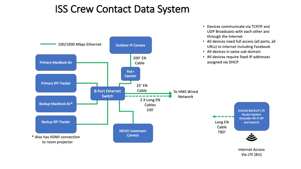
The final element in our plan is the Data System. The network at HMS is very tightly controlled from a security point of view, making it difficult to use for contact critical functions like access to up-to-date Keplerian Elements for our straightforward. Dave has an LTE-based Internet Access System that we have used in the past and elected to use to support our stations. We are planning to use the HMS network to transport the Livestream video from our contact. We’ll be using a Mevo Internet Camera for this purpose.
A Million Details…
As you can probably imagine, many details go into making a project like this possible. Here’s a rough timeline of some of the major remaining steps from a Ground Station point of view:
- Assemble both stations at our QTH with the 2m amplifier and the final 215′ control cables and feed lines – In progress and should be complete in a few days.
- Full Station Test – add the Audio and Data System components and test the full station at our QTH – Within a week.
- Configure and Test Data Network Access – for Live Streaming Video and the computers.
- Set up Ground Station at HMS and perform Dry Run Test – Complete by December 1st.
Dan and the HMS faculty team are also very busy finalizing the student’s questions and handling press-related activities.
We hope our readers will join us via the Livestream video for our contact. We’ll post more on this as we get closer!
Fred, AB1OC
If you have found a spelling error, please, notify us by selecting that text and pressing Ctrl+Enter.

THANKS very much for your well documented efforts. Inspired by your designs, I have begun construction of a ground station based on your 2.0 system. Eric K7EAS
Thank you Eric. You’re welcome to post comments here if you have questions as you go. I’ll be glad to try to help.
– Fred, AB1OC
Appreciate your kind offer of help. Can you help me get the Raspberry Pi image for the interface between MacDoppler and Green Heron controller? I have asked Jeff at Green Heron, and he is trying to contact the developer of the image — might that be you?
Hi Eric,
Yes, Jeff did reach out to me and posting the image is on my ToDo list. Standby for a week or two and I should have some that I can post.
Fred, AB1OC